

 Italiano
Shop
Showing 151–180 of 1386 results


-
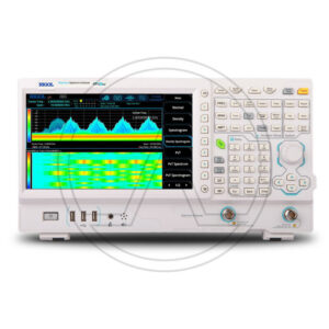
Spectrum Analyzer - Analizzatore di Spettro
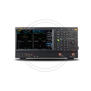
RIGOL RSA5032N

For all new order of RSA5000N versions we providing free of chargeand Pre-Amplifier Option (RSA5000-B40 and RSA5000-PA)
The Real-Time Spectrum Analyzers of the RSA 5000 family simplify the monitoring and characterization of RF devices such as, for example, WiFi and Bluetooth.
The RSA5000 series real-time spectrum analyzer integrates in a single instrument five measurement modes to fully address all the demands posed by the recent and increasingly sophisticated RF test requirements.
In addition to the traditional GPSA mode, EMI, RTSA, VSA and VNA modes are offered. This tool reduces the time and cost of RF test development and with its performance greatly improves the development and testing of RF products. The user interface is clear and allows you to operate in different ways, buttons on the front panel, touch screen, mouse and keyboard. Remote communication interfaces are also available.
It is a very versatile tool and can be used with excellent results indifferently in education, in R&D, in industrial production.Features:
-Ultra-Real technology
-Displayed average noise level (DANL): <-165 dBm (typical)
-Phase noise: <-108 dBc/Hz (typical)
-Level measurement uncertainty: <0.8 dB
-Min. RBW 1 Hz
-Multiple measurement modes
-Various advanced measurement functions
-Multiple trigger modes and trigger masks
-Density, spectrogram, and other display modes
-PC software options
-10.1'' capacitive multi-touch screen, supporting touch gestures-USB, LAN, HDMI and other communication and display interfaces
SKU: n/a€7,890.00 View Product -
Spectrum Analyzer - Analizzatore di Spettro
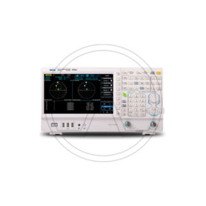
RIGOL RSA3045N

For all new order of RSA3000N versions (not valid for RSA3000E versions) we providing free of charge EMI
and Pre-Amplifier Option (RSA3000-EMI and RSA3000-PA)The RSA3000 series, real-time spectrum analyzer integrates in a single instrument four measurement modes to face in the most complete way all the demands posed by the recent and increasingly sophisticated RF test requirements.
In addition to the traditional GPSA mode, EMI, RTSA and VNA modes are offered. This tool reduces the time and cost of RF test development and with its performance greatly improves the development and testing of RF products. The user interface is clear and allows you to operate in different ways, buttons on the front panel, touch screen, mouse and keyboard. Remote communication interfaces are also available.
It is a very versatile tool and can be used with excellent results indifferently in education, in R&D, in industrial production.Features:
-Ultra real technology
Average Display Noise Level (DANL): <-161 dBm (typical)
Phase noise: <-102 dBc / Hz (typical)
– Level measurement uncertainty: <1.0 dB
-4.5 GHz tracking generator
– Up to 40 MHz of bandwidth for real-time analysis
-Multiple measurement modes
-Various advanced measurement functions
-EMI measurement application (option)
– Vector network analyzer application
-Multiple trigger modes and trigger masks
-Density, spectrogram and other display modes
– PC software options
-10.1 '' capacitive multi-touch screen; support tactile gestures
-USB, LAN, HDMI and other communication and display interfaces
DatasheetSKU: n/a€6,190.00 View Product -
Spectrum Analyzer - Analizzatore di Spettro
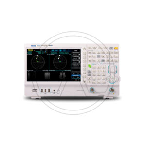
RIGOL RSA3030N

For all new order of RSA3000N versions (not valid for RSA3000E versions) we providing free of charge EMI
and Pre-Amplifier Option (RSA3000-EMI and RSA3000-PA)The RSA3000 series, real-time spectrum analyzer integrates in a single instrument four measurement modes to face in the most complete way all the demands posed by the recent and increasingly sophisticated RF test requirements.
In addition to the traditional GPSA mode, EMI, RTSA and VNA modes are offered. This tool reduces the time and cost of RF test development and with its performance greatly improves the development and testing of RF products. The user interface is clear and allows you to operate in different ways, buttons on the front panel, touch screen, mouse and keyboard. Remote communication interfaces are also available.
It is a very versatile tool and can be used with excellent results indifferently in education, in R&D, in industrial production.Features:
-Ultra real technology
Average Display Noise Level (DANL): <-161 dBm (typical)
Phase noise: <-102 dBc / Hz (typical)
– Level measurement uncertainty: <1.0 dB
-4.5 GHz tracking generator
– Up to 40 MHz of bandwidth for real-time analysis
-Multiple measurement modes
-Various advanced measurement functions
-EMI measurement application (option)
– Vector network analyzer application
-Multiple trigger modes and trigger masks
-Density, spectrogram and other display modes
– PC software options
-10.1 '' capacitive multi-touch screen; support tactile gestures
-USB, LAN, HDMI and other communication and display interfaces
DatasheetSKU: n/a€2,990.00€4,990.00View Product -
Spectrum Analyzer - Analizzatore di Spettro
RIGOL RSA3015N

For all new order of RSA3000N versions (not valid for RSA3000E versions) we providing free of charge EMI
and Pre-Amplifier Option (RSA3000-EMI and RSA3000-PA)The RSA3000 series, real-time spectrum analyzer integrates in a single instrument four measurement modes to face in the most complete way all the demands posed by the recent and increasingly sophisticated RF test requirements.
In addition to the traditional GPSA mode, EMI, RTSA and VNA modes are offered. This tool reduces the time and cost of RF test development and with its performance greatly improves the development and testing of RF products. The user interface is clear and allows you to operate in different ways, buttons on the front panel, touch screen, mouse and keyboard. Remote communication interfaces are also available.
It is a very versatile tool and can be used with excellent results indifferently in education, in R&D, in industrial production.Features:
-Ultra real technology
Average Display Noise Level (DANL): <-161 dBm (typical)
Phase noise: <-102 dBc / Hz (typical)
– Level measurement uncertainty: <1.0 dB
-4.5 GHz tracking generator
– Up to 40 MHz of bandwidth for real-time analysis
-Multiple measurement modes
-Various advanced measurement functions
-EMI measurement application (option)
– Vector network analyzer application
-Multiple trigger modes and trigger masks
-Density, spectrogram and other display modes
– PC software options
-10.1 '' capacitive multi-touch screen; support tactile gestures
-USB, LAN, HDMI and other communication and display interfacesSKU: n/a€1,690.00€2,090.00View Product -
Spectrum Analyzer - Analizzatore di Spettro
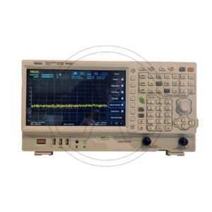
RIGOL RSA3030E

he Rigol RSA3000E series is a compact and light weight spectrum analyzer series with premium performance standard spectrum analysis capabilities combined with a Real-Time Spectrum Analyzer which makes it possible to never miss any signal that is longer than 7.45 µs in duration. Engineers integrating WiFi, Bluetooth and other modern RF technologies are confronted with complex challenges like frequency hopping signals, channel conflict, and spectrum interference.
Real-Time Spectrum Analyzers bring the dimension of time to RF Analysis making it easier to monitor and characterize these complex RF systems.
The RSA3000E combines industry leading Realtime performance (7.45µs 100% POI), rich data displays, and advanced triggering options allowing the user to quickly capture, identify and analyze these complex events.
Rigol's new RSA3000E series spectrum analyzers redefines the product category of general purpose spectrum analyzer by adding Real-Time spectrum trigger and analysis capabilities and sets a new level performance and price.
The RSA3000E family features a 10.1” touchscreen display, compact design and easy-to-use interface and operations, making it ideal for benchtop or field apps in RF and wireless testing and production such as IoT, RFID, analog and digital modulated signals.Embedded-System-Designer can cross trigger and analyze bus signals like IC2, SPI with RF Signals.
The Real-Time-Bandwidth of 10 MHz and the Frequency-Mask-Trigger let you visualize, isolate and capture signals to analyze their behavior over amplitude, frequency and time.
The new spectrum analyzer offers the ability to trigger and capture signals by 100% if longer than 7.45 µs in duration.
The RSA3000E have RBW settable down to 10 Hz, a DANL (displayed average noise level) down to -161 dBm (typical) and a 1ms Full Span Sweep in its general-purpose spectrum analyzer mode.
EMI filter and detector such as 9KHz, 120kHz and Quasi-Peak as example are standard.
Extendibility: Pre-Amplifier, High Stability Clock, Advanced Measurement Kit, EMI Pre-compliance Test Software can be added optional.Features
9 kHz to 3 or 4.5 GHz Frequency Range
10.1” Capacitive touchscreen display
Displayed Average Noise Level as low as -161 dBm with opt. PreAmplifier
Real-Time Analysis Bandwidth of 10 MHz standard (40 MHz option)
Frequency-Mask-Trigger, IF-Power-Level-Trigger and external Trigger
7 Real-Time visualization modes
100 % POI as low as 7. 45 µs
10 Hz Minimum Resolution Bandwidth (RBW) (1 Hz option)
1 ms full span sweep speed
EMI RBW and Detector standard (200 Hz, 9 kHz, 120 kHz, 1 MHz)
Tracking Generator and VSWR measurements availableSKU: n/a€2,999.00€3,199.00View Product -
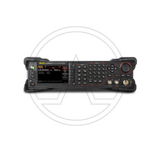
Signal Generator
RIGOL DSG3065B-IQ

The DSG3000B series is a high-performance RF signal generator. It provides comprehensive modulation solutions: AM/FM/ΦM analog modulation; pulse modulation with user-defined pulse train; and I/Q modulation. All the modulations support internal and external modulation sources. In addition, to meet the demands of production environments, the DSG3000B series has undergone a strict verification through the experiments in its design and
production stages to ensure its high stability and reliability. The DSG3000B series also features a clear user interface, compact size and light weight. It is easy to operate and can output stable, precise and pure signals. It is an ideal tool in various fields such as communication, computers, instrumentation, R&D, education, production and maintenance.Features:
Highest frequency: 6.5GHz
Amplitude accuracy: <0.5 dB (typical) Output amplitude range: -130 dBm to +27 dBm (setting range) High signal purity, phase noise: <-116 dBc/Hz@20 kHz (typical) Standard 1 ppm internal clock; optional 5 ppb high stable clock Standard AM/FM/ΦM analog modulation Support pulse modulation; on/off ratio up to 70 dB; user-defined pulse train generator I/Q modulation and I/Q baseband output All modulations support internal and external modulation modes Standard 2U height design to save rack space; rack mount kit is available Support USB/LAN/GPIB remote control; SCPI command set Wear-free electronic attenuator design DatasheetSKU: n/a€10,599.00 View Product -
Signal Generator
RIGOL DSG3065B

The DSG3000B series is a high-performance RF signal generator. It provides comprehensive modulation solutions: AM/FM/ΦM analog modulation; pulse modulation with user-defined pulse train; and I/Q modulation. All the modulations support internal and external modulation sources. In addition, to meet the demands of production environments, the DSG3000B series has undergone a strict verification through the experiments in its design and
production stages to ensure its high stability and reliability. The DSG3000B series also features a clear user interface, compact size and light weight. It is easy to operate and can output stable, precise and pure signals. It is an ideal tool in various fields such as communication, computers, instrumentation, R&D, education, production and maintenance.Features:
Highest frequency: 6.5GHz
Amplitude accuracy: <0.5 dB (typical)
Output amplitude range: -130 dBm to +27 dBm (setting range)
High signal purity, phase noise: <-116 dBc/Hz@20 kHz (typical)
Standard 1 ppm internal clock; optional 5 ppb high stable clock
Standard AM/FM/ΦM analog modulation
Support pulse modulation; on/off ratio up to 70 dB; user-defined pulse train generator
I/Q modulation and I/Q baseband output
All modulations support internal and external modulation modes
Standard 2U height design to save rack space; rack mount kit is available
Support USB/LAN/GPIB remote control; SCPI command set
Wear-free electronic attenuator designSKU: n/a€7,299.00 View Product -
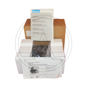
MOTOROLA STORNO CPQ7000 SINGLE UNIT RAPID RATE CHARGE–ELN1022A

The CQP7000 was introduced to the Storno model line-up in 1988. There were three basic models, no keypad, limited keypad with display and full keypad with display. Known as the CQP7000a, b and c they were the Storno branded versions of the Motorola MX1000, 2000 and 3000. A wide variety of specific models and options were available with up to 100 channels and transmit powers up to 6W VHF and 5W at UHF.
The Storno 7000 was constructed in three main parts, the radio housing and baseplate assembly which had all the front and side button actuators and contacts for the separate battery. The internals consisted of the front shield which carried the LCD display, speaker, keypad membrane, personality EEPROM and controller of the peripheral electronics (COPE). The front shield clipped over the frame assembly which housed the top panel controls, the main circuit board with controller of the radio electronics (CORE), and the plug-in RF modules.
The CQP7000 supported a wide range of tone signalling standards, channel scanning and user programmable memory features, enhanced by the eight character alphanumeric display. Special options included submersible, encrypted, intrinsically safe and Storno PhoneNet 2200 trunked system compatible versions..
DatasheetSKU: n/a -
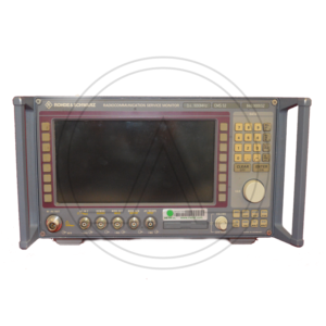
ROHDE & SCWARZ CMS52

ROHDE & SCWARZ CMS52 RADIOCOMMUNICATION SERVICE MONITOR 0.4 to 1000 MHz
Options included:
B1/B2 > OCXO
B39 > Transf., Contr., Interf.
B59 > DuplexThe CMS radiocommunication service monitor is the ideal radio tester for use in service, maintenance, and test departments. It is suitable for all transceivers using AM, FM or, jM as well as SSB.
Optional extensions enable the CMS to satisfy all requirements of radio measurements and even to cover related fields.
Low weight, compact size, and low power consumption make this instrument particularly suitable for mobile use. Whether stationary or mobile, the CMS with its extensive test facilities always provides a valuable service.
The CMS uses a high-contrast, backlit LCD screen with high resolution and is operated via softkeys. A clear menu structure allows fast and direct access to all measurement facilities.
With the autorun control and printer interface, automatic test routines can easily be configured and stored via the front-panel keypad. Tolerances can be inserted into these test routines to determine and log pass/fail limits.
Battery-backed memory cards are used as program and test report library. Test reports, program lists, and screen hardcopies can be output on a printer.
The CMS is a rugged and handy unit that is particularly suitable for mobile use. It can be supplied from the local DC voltage (long operating times due to low power consumption). The results of the automatic transceiver test can be stored on a memory card for later analysis and printout.
The CMS offers great benefits to the development engineer: In a minimum of space it combines RF and AF generators as well as analyzers with high accuracy and wide dynamic range.
Due to the comprehensive standard configuration of the individual ¸CMS models and the optional extensions tailored to specific applications, additional external measuring instruments are not required.
Signal sources
• RF synthesizer from 0.4 MHz to 1000 MHz, resolution 10 Hz, with AM, FM, jM, and multitone modulation capabilities
• Two independent modulation generators, 20 Hz to 30 kHz each, resolution 0.1 Hz
• Selective-call coder for all standards (also user-programmable)
• CDCSS coder
• DTMF coder
• 10 MHz reference frequency input/output
• VOR/ILS signal generatorMeasuring facilities
• RF frequency counter, RF frequencyoffset counter
• RF power meter from 1 mW to 100 W
• Selective RF power meter down to –100 dBm
• RF spectrum monitor with wide dynamic range and filters that also allow modulation analysis (AM, FM, SSB)
• Tracking generator in frequency range from 400 kHz to 1000 MHz
• Adjacent-channel power meter with standard ETSI filters
• Modulation meter for AM, FM, and jM; detectors: +PK, –PK, PK HOLD, ±PK/2, RMS, RMS √2
• Duplex modulation meter for duplex spacings of any size
• AF voltmeter with peak and true RMS weighting
• SINAD meter with variable test frequency
• S/N meter
• Distortion meter with variable test frequency
• AF frequency counter with period and gate-time counting
• Selective-call decoder for all standards (also user-programmable)
• DTMF decoder
• Oscilloscope
• DC ammeter/voltmeter T
• ransient recorder for analysis of power and frequency transients
• SSB menus
• Harmonic measurements
• Cable fault finder
DatasheetSKU: n/a -
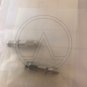
Coaxial Dual-Directional Coupler
FAIRVIEW MICROWAVE SD3241

Coaxial DC block SD3241 is only one of a large number of radio frequency DC blocking components specifically stocked to be ready for quick shipment. Fairview Microwave RF DC block is manufactured with a SMA connector in and SMA connector out. Our SMA to SMA DC block is male to female genders in and out.
Fairview Microwave SMA DC block has a 50 Ohm impedance and an inner design. Our 50 Ohm SMA inner DC block is rated for a minimum frequency of 10 MHz and a maximum frequency of 18 GHz. SD3241 SMA inner DC block has a maximum insertion loss of 1 dB and a maximum VSWR of 1.35:1.
Inner DC block specs for this Fairview direct current blocking component can be found on its DC block datasheet PDF specifications above. Inner SMA DC block is one radio frequency component of more than one million microwave and millimeter wave RF parts in stock at Fairview and is ready to buy and can be shipped worldwide. Fairview also maintains a wide selection of other radio frequency DC blocks that ship same-day from our Allen, TX warehouse in the as with the rest of our other RF/microwave and millimeter wave components.Block Type Inner
Impedance 50 Ohm
Connector In Series SMA
Connector In Gender Male
Connector Out Series SMA
Connector Out Gender Female
Minimum Frequency 10 MHz
Maximum Frequency 18 GHz
Maximum VSWR 1.35:1
Maximum Voltage 50 Volts
DatasheetSKU: n/a -
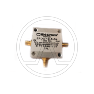
Directional Couper
Mini-Circuits ZFDC-10-5-S+

Mini-Circuits ZFDC-10-5-S+ is a 10.8 dB Directional Coupler, 1 – 2000 MHz, 50Ω
Connector Type: SMA
Features
• very wideband, 1 to 2000 MHz
• excellent directivity, 30 dB typ.
• rugged shielded caseApplications
• cellular
• instrumentation
• communication receivers & transmitters
• GPS
DatasheetSKU: n/a -
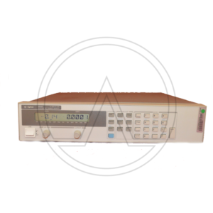
Power Supply
AGILENT-Hp/Keysight 6645A

Questa serie di alimentatori CC regolati lineari da 200 W è progettata per massimizzare la produttività dei DUT attraverso il processo di test di produzione con tempi di programmazione rapidi su e giù.
I preziosi insiemi possono essere distrutti da un guasto minore di un componente che può consentire un flusso di tensione o corrente che fluisce verso il DUT. Le funzioni di protezione rapida, tra cui il piede di porco rapido, la protezione crossover in modalità e la possibilità di collegare i circuiti di protezione di più alimentatori possono aumentare il rendimento di produzione.
La programmazione dell'uscita CC e delle funzioni di protezione può essere effettuata dal pannello frontale o utilizzando i comandi SCPI standard del settore, tramite GPIB. Utilizzando il collegamento seriale, è possibile collegare fino a 16 alimentatori tramite un indirizzo GPIB. L'integrazione del sistema di test può essere ulteriormente semplificata utilizzando i driver VXIplug & play. La tensione e la corrente di uscita possono anche essere controllate con segnali analogici. Ciò è utile per alcuni tipi di ambienti rumorosi e anche per reazioni immediate ai cambiamenti di processo.Tensione flottante CC: i terminali di uscita possono essere fatti galleggiare fino a ± 240 V CC dalla terra del telaio.
Telerilevamento: è possibile far cadere fino a metà della tensione di uscita nominale in ciascun cavo di carico. La caduta del carico comporta la sottrazione della tensione disponibile per il carico.
Tempo di elaborazione del comando: il tempo medio necessario affinché la tensione di uscita inizi a cambiare in seguito alla ricezione di dati digitali è di 20 ms per gli alimentatori collegati direttamente al GPIB.
Tempo di risposta della programmazione dell'uscita: il tempo di salita e discesa (10/90% e 90/10%) della tensione di uscita è inferiore a 15 ms. La variazione della tensione di uscita si assesta entro 1 LSB (0,025% x tensione nominale) del valore finale in meno di 60 ms.
Programmazione verso il basso: un programmatore attivo verso il basso affonda circa il 20% della corrente di uscita nominale.Valori nominali di uscita
Tensione di uscita: da 0 a 120 V.
Corrente di uscita (40 ° C): da 0 a 1,5 A
Corrente massima (50 ° C / 55 ° C): 1,4 A / 1,3 APrecisione di programmazione a 25 ° C ± 5 ° C
Tensione 0,06% + 51 mV
Corrente 0,15% + 1,7 mARipple & Noise (20 Hz – 20 MHz)
Voltaggio rms: 700 µV
Tensione picco-picco: 7 mV
Corrente efficace: 1 mA
Scheda TecnicaSKU: n/a -
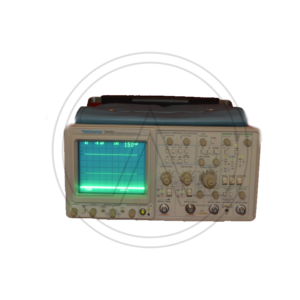
Oscilloscope 4 channles
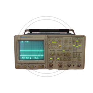
TEKTRONIX 2445

the Tektronix 2445 is a four-channel 150 MHz portable oscilloscope.
Bandwidth 150 MHz
Sweep Rate 500 ps/div
Channels Four independent channels
Vertical 2 mV/div vertical sensitivity
Cursors Delta Volts and Delta Time Cursors
CRT Readout Scale Factors, Trigger Level, Voltage, Time, Frequency, Phase and Ratio Measurements and Mode Indicators
Trigger Advanced Triggering with “Hands Off” Auto Level Triggering
Trigger Bandwidth 500 MHz min.
Input Impedance 50 Ω/1 MΩ inputs with 50 Ω protection
Probes Two P6131 ×10 probes, 1.3 m
DatasheetSKU: n/a -
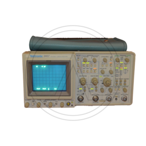
Oscilloscope 4 channles
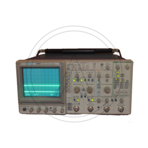
TEKTRONIX 2467

TEKTRONIX 2467 FOUR-CHANNEL 350 MHz PORTABLE OSCILLOSCOPE
The 2467 is the same as the 2465A, except that the 2465A uses a conventional CRT while the 2467A uses a micro-channel plate CRT. The MCP CRT enables bright traces at fast sweep rates, particularly with one-shot or low repetition rate signals.Bandwidth 350 MHz
Sweep Rate 500 ps/div
Channels Four independent channels
Vertical 2 mV/div vertical sensitivity
Cursors Delta Volts and Delta Time Cursors
CRT Readout Scale Factors, Trigger Level, Voltage, Time, Frequency, Phase and Ratio Measurements and Mode Indicators
Trigger Advanced Triggering with “Hands Off” Auto Level Triggering
Trigger Bandwidth 500 MHz min.
Input Impedance 50 Ω/1 MΩ inputs with 50 Ω protection
Probes Two or four P6136 ×10 probes, 1.3 m
DatasheetSKU: n/a -
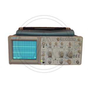
Oscilloscope 2 channels
TEKTRONIX 2230

The Tektronix 2230 is a portable 100 MHz, dual-channel combination analog / digital storage scope, sister model of 2220 and 2221.
It has both an analog mode and a digital mode. In the digital storage mode, up to three waveform sets (CH 1 and/or CH 2) may be stored in a save ref. memory and recalled for display at a later time.
The 2230 features alphanumeric CRT readout of many of the front panel controls. It has a DB-9 auxiliary connector on the right side providing an external clock input as well as an output for an analog X-Y plotter to make permanent copies of the display. This feature can be accessed through the “Mem select” menu.
Some Firmware versions have a diagnostics menu with the Tektronix logo and wizard image.Vertical —
Input impedance 1 MΩ // 20 pF
Maximum Safe Input Voltage 400 V (dc + peak AC) or 800 Vp-p AC
CMRR At least 10:1 at 10 MHz
— Horizontal —
Timebase A 50 ns/Div to 0.5 s/Div, 1-2-5, x10 magnifier, i.e. down to 5 ns/Div. In “Store” mode lower sweep speeds up to 5 s/Div are available
Timebase B 50 ns/Div to 5 s/Div, 1-2-5, x10 magnifier, i.e. down to 5 ns/Div
Bandwidth 100 MHz (analog)
Sampling rate 20 MS/s
Record length 1K or 4K samples (single channel), optional 26K
Z axis input (intensity); DC to 20 MHz, maximum safe input 30V (dc + peak ac) Input resistance about 10kΩ
CRT display area : 8 × 10 cm²
Dimensions With feet and handle: 137 x 361 x 511 mm³
Features · X-Y operation
· Pre/Post-triggering
· Averaging
· Dual time base
· Cursors and readout
DatasheetSKU: n/a -
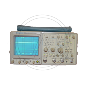
Oscilloscope 4 channles
TEKTRONIX 2465

The Tektronix 2465 is a four-channel 300 MHz portable oscilloscope.
The 2465 is from the penultimate generation of analog Tektronix scopes.
The horizontal amplifier in the 2465 was designed by Art Metz and Ken Schlotzhauer. Art Metz also worked on the triggers. Art Metz and Walt Ainsworth designed the sweeps.
Sweep Rate 500 ps/div
Channels Four independent channels
Vertical 2 mV/div vertical sensitivity
Cursors Delta Volts and Delta Time Cursors
CRT Readout Scale Factors, Trigger Level, Voltage, Time, Frequency, Phase and Ratio Measurements and Mode Indicators
Trigger Advanced Triggering with “Hands Off” Auto Level Triggering
Trigger Bandwidth 500 MHz min.
Input Impedance 50 Ω/1 MΩ inputs with 50 Ω protectionSKU: n/a -
Oscilloscope 4 channles
TEKTRONIX 2465A

The Tektronix 2465A is a four-channel 350 MHz portable oscilloscope. The 2445A and 2455A are 150 and 250 MHz versions.
The horizontal amplifier in the 2465A was designed by Art Metz and Ken Schlotzhauer.
Art Metz also worked on the triggers. Art Metz and Walt Ainsworth designed the sweeps.Sweep Rate 500 ps/div
Channels Four independent channels
Vertical 2 mV/div vertical sensitivity
Cursors Delta Volts and Delta Time Cursors
CRT Readout Scale Factors, Trigger Level, Voltage, Time, Frequency, Phase and Ratio Measurements and Mode Indicators
Trigger Advanced Triggering with “Hands Off” Auto Level Triggering
Trigger Bandwidth 500 MHz min.
Input Impedance 50 Ω/1 MΩ inputs with 50 Ω protection
Probes Two or four P6136 ×10 probes, 1.3 m
DatasheetSKU: n/a -
Oscilloscope 4 channles
TEKTRONIX 2246A

The Tektronix 2246 is a 100 MHz four-channel analog oscilloscope. Channels 1-2 are fully-functional, whereas 3-4 are limited in both deflection factor and coupling, as they are intended mainly for digital and trigger signals.
The 2246 includes many of the same features of the 2245A and adds auto tracking SmartCursors which track the selected measurment, trigger level, or ground. There are Labeled Volts Cursors with Ground-Referenced Readings and On-Screen Readouts; Hands-Off Voltmeter Measurements of DC Volts, +Peak and -Peak Volts, and P-P Volts; SmartCursors Integrate Voltage, Time, Frequency, and Phase Measurements, and are available in ALT and B Horizontal Modes.
Bandwidth 100 MHz
Deflection CH 1, CH 2: 2 mV/div to 5 V/div in 1-2-5 seq; CH 3, CH 4: 0.1 V/div and 0.5 V/div, all ±2%; BW Limit: 20 MHz ±15%
Vertical Operating Modes CH1,2,3,4, CH2 Invert, Add, Alt, Chop (625 kHz)
Input Impedance 1 MΩ ±1.0% // 20 pF ±1 pF
Maximum Input Voltage 400 V (DC + peak AC) or 800 V (p-p ac at ≤ 10 kHz)
Sweep Speeds A Time Base: 0.5 s/div to 20 ns/div in 1-2-5 seq; B Time Base: 5 ms/div to 20 ns/div in 1-2-5 seq (×10 magnifier to 2 ns/div)
Trigger DC, Noise Reject, HF Reject, LF Reject, AC, TV Line, TV Field
Trigger Modes A Mode: Auto Level, Auto, Norm, TV Line, TV Field, Single Seq. B Mode: Runs After Delay, Auto Level, Norm, TV Line (From A Source)
Trigger Source A & B Vert, CH1, 2, 3, 4, Line
Voltmeter DC, +Peak, −Peak, PK-PK, Gated Volts, Smart Tracking Cursors: Volts, Gnd, Trigger Lvl
Cursors Time, 1/Time, Delta Time, 1/Delta Time, Delta Phase, Volts
Interface Ext Counter/Timer Base Input connector; Ext Z-Axis Input connector
Probes Two P6109 100 MHz ×10 probes, BNC Connector with a readout pin.
Power 100 W max, 90 − 250 VAC, 48 − 445 Hz
DatasheetSKU: n/a -
OSCILLOSCOPE COUNTER / TIMER / MULTIMETER
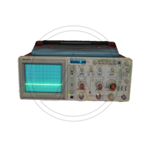
TEKTRONIX 2236

The Tektronix 2236 is a 100 MHz portable scope with a dual time base and a built-in DMM/counter with a dedicated 9-digit VF display. Apart from the counter, it is the same as the 2235.
In addition to signal frequency and period, the counter can measure delay time and delta time from the delayed timebase.
Bandwidth 90 MHz at 2 mV/Div, 100 MHz at 5 mV/Div and above; switchable 20 MHz limit
Rise time 3.9 ns at 2 mV/Div, 3.5 ns at 5 mV/Div and above
Deflection 2 mV/Div to 5 V/Div, 1−2−5, ±2%, and variable 2.5:1
Time base 50 ns/Div to 500 ms/Div (B timebase to 50 ms/Div), 1−2−5, ×10 magnifier for fastest deflection of 5 ns/Div
Frequency counter 7 digit resolution; frequency 100 Hz to 100 MHz in decade ranges, period 100 μs to 1 s in decade ranges, plus 5 s range; time base accuracy 1×10⁻⁵ (Opt.14: 5×10⁻⁷), sensitivity same as trigger specs
Multimeter 3¾ digit resolution, ≥2.5 measurements per second, 10 MΩ input resistance, input isolated from scope ground; DC volts 0.5 V to 500 V in decade ranges; AC volts RMS 0.5 V to 350 V in decade ranges; resistance 50 Ω to 50 MΩ in decade ranges, plus 200 MΩ and 2 GΩ ranges; temperature -62 °C to +230 °C (with P6602 probe)
Input impedance 1 MΩ // 20 pF
Trigger sensitivity 0.3 Div or 35 mV up to 10 MHz, 1 Div or 120 mV up to 60 MHz, 1.5 Div or 200 mV up to 100 MHz
CRT 80×100 mm² display area, P31 phosphor, 14 kV acceleration voltage
Power 90−250 VAC, 48 to 440 Hz, 40 W
Size 137 mm × 328 mm × 440 mm (5.4″ × 12.9″ × 17.3″)
Weight 5.2 kg (11.5 lb) without accessories
FeaturesDMM and counter
Delayed timebase
X−Y mode
Z input
DatasheetSKU: n/a -
Electronic Load Module
HP-Agilent/Keysight N3302A

Keysight N3302A è un modulo di carico elettronico da 150 W (0-30A, 0-60 V) per l'utilizzo nel mainframe di carico elettronico N3300A o N3301A nelle applicazioni di sistema. Il modulo di carico N3302A è rapido e preciso, per la programmazione in modalità corrente costante, tensione costante o resistenza costante o per effettuare misurazioni di tensione, corrente o potenza. L'N3302A può anche digitalizzare forme d'onda.
Il test di più alimentatori cc e convertitori cc / cc può richiedere molto tempo se ogni uscita deve essere testata in sequenza. Se le misurazioni vengono eseguite tramite un MUX utilizzando un DMM, questo è ciò che accadrà. Utilizzando le capacità di misurazione integrate dei carichi elettronici N3300A, è possibile misurare contemporaneamente tutte le uscite. In alternativa, è possibile testare contemporaneamente più fonti di alimentazione a uscita singola.
È sufficiente un unico indirizzo GPIB per il controllo completo e la rilettura del modulo di carico N3302A all'interno di un singolo mainframe N3300A o N3301A. Il carico elettronico N3302A offre un funzionamento rapido e la programmazione e la lettura accurate necessarie per i sistemi di test dell'alimentazione CC ad alto volume.
Valutazioni di input
Corrente: 0-30 A
Voltaggio: 0 – 60 V.
Potenza massima: 150 W.Modalità corrente costante
Low Range / High Range: 3 A / 30 A
Regolazione: 10 mA
Precisione gamma bassa: 0,1% + 5 mA
Precisione gamma alta: 0,1% + 10 mAModalità a tensione costante
Low Range / High Range: 6 V / 60 V
Regolamento: 5 mV
Precisione gamma bassa: 0,1% + 3 mV
Precisione di alta gamma: 0,1% + 8 mVModalità di resistenza costante
Intervallo 1 (I> 10% della corrente nominale): 0,067-4 Ω
Intervallo 2 (I> 1% della corrente nominale): 3,6-40 Ω
Intervallo 3 (I> 0,1% della corrente nominale): 36-400 Ω
Intervallo 4 (I> 0,01% della corrente nominale): 360-2000 Ω
Scheda TecnicaSKU: n/a -
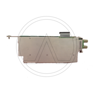
Module
HP-Agilent/Keysight N6731B

Keysight basic modules provide stable output, device protection, and accurate measurements. A single range allows programming voltages and currents from 0 V and 0 A to their maximum voltage and current rating. Use 2-wire local sense or 4-wire remote sense to improve regulation. All modules feature a quick disconnect connector.
Programmable output voltages: 0 to 150 V
Output power: 50 to 300 W
Voltage accuracy: 0.1% + 19 mV (5V output)
Ripple and noise 10 mV (5V output)
Up and down-programming with resistive load typically 20 msOvervoltage, overcurrent, and overtemperature protection
Basic modules are single wide allowing four per mainframe
Modules can operate at lower output power to stay within mainframe rating
Modules include a quick disconnect connector
DatasheetSKU: n/a -
Power Source / Power Analyzer
HP-Agilent/Keysight 85901A

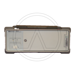
The Keysight 85901A Portable AC Power Source works with your test equipment to provide the power you need, where you need it. The power source is small, with a briefcase handle that makes it easy to carry and it fits into tight spots. You can use the built-in battery of the power source or connect it to an external 12 Vdc source for even longer operation.
200 Watts continuous output
115 Vrms or 230 Vrms output
Internal battery or external 12 Vdc source
Built-in charger
Up to 2 hour operation of Keysight 8590 Series Spectrum Analyzers
Easy to carry
DatasheetSKU: n/a -
Network Analyzer
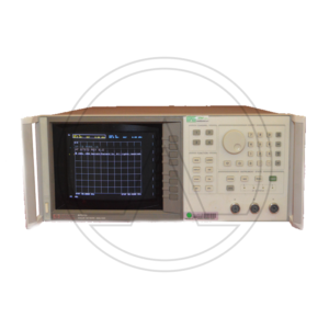
HP-Agilent/Keysight 8757D LCD

The HP 8757D LCD COLOR DISPLAY scalar network analyzer allows you to measure insertion loss, gain, return loss, SWR, and power quickly and accurately . With high-performance detectors and directional bridges, and a companion Keysight source and printer, this analyzer becomes the basis of a complete measurement system with superb performance.
Setup time is reduced by external disk save/recall, and measurement data can be sent directly to a printer while you proceed to the next measurement.
You can configure your system using a Keysight PSG signal generator with ramp sweep capability. The dynamic range can be extended from 75 dB to 83 dB using the PSG's high power option.
The Agilent 8757D has four independent display channels that process the signals from the Agilent 85037 series precision detectors, 85025 and 85026 detectors, and the 85027 series directional bridges for logarithmic display, in single channel or ratio mode. Three (optionally four) detector inputs are provided.
The number of points (horizontal resolution) that can be selected depends on the number of traces displayed.
A display is considered faulty if:
• A complete row or column of “stuck” or “dark” pixels.
• More than six “stuck on” pixels (but not more than three green) or more than 0.002% of the total pixels are within the LCD specifications.
• More than twelve “dark” pixels (but no more than seven of the same color) or more than 0.004% of the total pixels are within the LCD specifications.
• Two or more consecutive “stuck on” pixels or three or more consecutive “dark” pixel (but no more than one set of two consecutive dark pixels) “Stuck on” of “dark” pixels less than 6.5 mm apart (excluding consecutive pixels.All analyzer display channels can display any one of the detector inputs or any ratio combination of detector inputs.
Log magnitude >
dBm: single channel power measurement
dB: relative power measurement (ratio or relative to trace memory)SWR > Relative measurements (normalized or ratio measurements) can be displayed in SWR. Channels 1 and 2 only: 401 points or fewer
AUX voltage > The rear panel BNC input ADC IN can be measured and displayed in volts (–10 to +10 volts). Typical maximum error is 60 mV.
Up to 8 operator-selectable colors are available for LCD attributes, such as the grid, measurement traces, and labels.
The minimum sweep time depends on the number of traces displayed and the number of points selected.
Traces are stored and normalized with the highest resolution, independent of display scale/division or offset. With adaptive normalization on the Agilent 8757D, calibration data is interpolated when the frequency span is decreased.
Key Features & SpecificationsUp to 83 dB dynamic range
Buffered plotter/printer output
Built-in limit testing for quick pass/fail decisions
External disc and internal register save/recall of test setups
Color display
Optional internal power meter calibrator and precision detectors provide near power meter accuracy
DISLPAY CRT
Four display channels
Three detector inputs
+16 to –60 dBm dynamic range
AC/DC detection modes
101 to 1601 measurement points/trace
Compatible with the Agilent 85025 and 85026 series detectors and the Agilent 85027 series directional bridges
Limit line testing (channels 1 and 2)
Adaptive normalization
Cursor search functions (max, min, n dB, BW)SKU: 69-1 -
HP 10240B

The HP 10240B Blocking Capacitor is a probing accessory that provides ac-coupling while maintaining a 50 ohm system. This capacitor is designed for use with the model HP 10020A Resistive Divider Kit, and the Keysight 54006A Resistive Divider Probe Kit, but may be used with any probe that must be terminated in 50 Ω.
* Provides ac-coupling
* Maintains a 50 ohm system
* Capacitance: 0.18 µF
* Maximum voltage: +/-200 Vdc
* Sag: Approximately 10% per µs (1% in 100 ns)
* Connectors: BNC
* Reflection: less than 12% when driven by a 150 ps risetime step in a 50 ohm system
* Capacitance: 0.18 µF
* Maximum voltage: +/-200 Vdc
* Sag: Approximately 10% per µs (1% in 100 ns)
* Connectors: BNC
* Reflection: less than 12% when driven by a 150 ps risetime step in a 50 ohm system
DatasheetSKU: n/a
-
Spectrum Analyzer - Analizzatore di Spettro
RIGOL RSA5032N
For all new order of RSA5000N versions we providing free of chargeand Pre-Amplifier Option (RSA5000-B40 and RSA5000-PA)
The Real-Time Spectrum Analyzers of the RSA 5000 family simplify the monitoring and characterization of RF devices such as, for example, WiFi and Bluetooth.
The RSA5000 series real-time spectrum analyzer integrates in a single instrument five measurement modes to fully address all the demands posed by the recent and increasingly sophisticated RF test requirements.
In addition to the traditional GPSA mode, EMI, RTSA, VSA and VNA modes are offered. This tool reduces the time and cost of RF test development and with its performance greatly improves the development and testing of RF products. The user interface is clear and allows you to operate in different ways, buttons on the front panel, touch screen, mouse and keyboard. Remote communication interfaces are also available.
It is a very versatile tool and can be used with excellent results indifferently in education, in R&D, in industrial production.Features:
-Ultra-Real technology
-Displayed average noise level (DANL): <-165 dBm (typical)
-Phase noise: <-108 dBc/Hz (typical)
-Level measurement uncertainty: <0.8 dB
-Min. RBW 1 Hz
-Multiple measurement modes
-Various advanced measurement functions
-Multiple trigger modes and trigger masks
-Density, spectrogram, and other display modes
-PC software options
-10.1'' capacitive multi-touch screen, supporting touch gestures-USB, LAN, HDMI and other communication and display interfaces
-
Spectrum Analyzer - Analizzatore di Spettro
RIGOL RSA3045N
For all new order of RSA3000N versions (not valid for RSA3000E versions) we providing free of charge EMI
and Pre-Amplifier Option (RSA3000-EMI and RSA3000-PA)The RSA3000 series, real-time spectrum analyzer integrates in a single instrument four measurement modes to face in the most complete way all the demands posed by the recent and increasingly sophisticated RF test requirements.
In addition to the traditional GPSA mode, EMI, RTSA and VNA modes are offered. This tool reduces the time and cost of RF test development and with its performance greatly improves the development and testing of RF products. The user interface is clear and allows you to operate in different ways, buttons on the front panel, touch screen, mouse and keyboard. Remote communication interfaces are also available.
It is a very versatile tool and can be used with excellent results indifferently in education, in R&D, in industrial production.Features:
-Ultra real technology
Average Display Noise Level (DANL): <-161 dBm (typical)
Phase noise: <-102 dBc / Hz (typical)
– Level measurement uncertainty: <1.0 dB
-4.5 GHz tracking generator
– Up to 40 MHz of bandwidth for real-time analysis
-Multiple measurement modes
-Various advanced measurement functions
-EMI measurement application (option)
– Vector network analyzer application
-Multiple trigger modes and trigger masks
-Density, spectrogram and other display modes
– PC software options
-10.1 '' capacitive multi-touch screen; support tactile gestures
-USB, LAN, HDMI and other communication and display interfaces
Datasheet -
Spectrum Analyzer - Analizzatore di Spettro
RIGOL RSA3030N
For all new order of RSA3000N versions (not valid for RSA3000E versions) we providing free of charge EMI
and Pre-Amplifier Option (RSA3000-EMI and RSA3000-PA)The RSA3000 series, real-time spectrum analyzer integrates in a single instrument four measurement modes to face in the most complete way all the demands posed by the recent and increasingly sophisticated RF test requirements.
In addition to the traditional GPSA mode, EMI, RTSA and VNA modes are offered. This tool reduces the time and cost of RF test development and with its performance greatly improves the development and testing of RF products. The user interface is clear and allows you to operate in different ways, buttons on the front panel, touch screen, mouse and keyboard. Remote communication interfaces are also available.
It is a very versatile tool and can be used with excellent results indifferently in education, in R&D, in industrial production.Features:
-Ultra real technology
Average Display Noise Level (DANL): <-161 dBm (typical)
Phase noise: <-102 dBc / Hz (typical)
– Level measurement uncertainty: <1.0 dB
-4.5 GHz tracking generator
– Up to 40 MHz of bandwidth for real-time analysis
-Multiple measurement modes
-Various advanced measurement functions
-EMI measurement application (option)
– Vector network analyzer application
-Multiple trigger modes and trigger masks
-Density, spectrogram and other display modes
– PC software options
-10.1 '' capacitive multi-touch screen; support tactile gestures
-USB, LAN, HDMI and other communication and display interfaces
Datasheet -
Spectrum Analyzer - Analizzatore di Spettro
RIGOL RSA3015N
For all new order of RSA3000N versions (not valid for RSA3000E versions) we providing free of charge EMI
and Pre-Amplifier Option (RSA3000-EMI and RSA3000-PA)The RSA3000 series, real-time spectrum analyzer integrates in a single instrument four measurement modes to face in the most complete way all the demands posed by the recent and increasingly sophisticated RF test requirements.
In addition to the traditional GPSA mode, EMI, RTSA and VNA modes are offered. This tool reduces the time and cost of RF test development and with its performance greatly improves the development and testing of RF products. The user interface is clear and allows you to operate in different ways, buttons on the front panel, touch screen, mouse and keyboard. Remote communication interfaces are also available.
It is a very versatile tool and can be used with excellent results indifferently in education, in R&D, in industrial production.Features:
-Ultra real technology
Average Display Noise Level (DANL): <-161 dBm (typical)
Phase noise: <-102 dBc / Hz (typical)
– Level measurement uncertainty: <1.0 dB
-4.5 GHz tracking generator
– Up to 40 MHz of bandwidth for real-time analysis
-Multiple measurement modes
-Various advanced measurement functions
-EMI measurement application (option)
– Vector network analyzer application
-Multiple trigger modes and trigger masks
-Density, spectrogram and other display modes
– PC software options
-10.1 '' capacitive multi-touch screen; support tactile gestures
-USB, LAN, HDMI and other communication and display interfaces -
Spectrum Analyzer - Analizzatore di Spettro
RIGOL RSA3030E
he Rigol RSA3000E series is a compact and light weight spectrum analyzer series with premium performance standard spectrum analysis capabilities combined with a Real-Time Spectrum Analyzer which makes it possible to never miss any signal that is longer than 7.45 µs in duration. Engineers integrating WiFi, Bluetooth and other modern RF technologies are confronted with complex challenges like frequency hopping signals, channel conflict, and spectrum interference.
Real-Time Spectrum Analyzers bring the dimension of time to RF Analysis making it easier to monitor and characterize these complex RF systems.
The RSA3000E combines industry leading Realtime performance (7.45µs 100% POI), rich data displays, and advanced triggering options allowing the user to quickly capture, identify and analyze these complex events.
Rigol's new RSA3000E series spectrum analyzers redefines the product category of general purpose spectrum analyzer by adding Real-Time spectrum trigger and analysis capabilities and sets a new level performance and price.
The RSA3000E family features a 10.1” touchscreen display, compact design and easy-to-use interface and operations, making it ideal for benchtop or field apps in RF and wireless testing and production such as IoT, RFID, analog and digital modulated signals.Embedded-System-Designer can cross trigger and analyze bus signals like IC2, SPI with RF Signals.
The Real-Time-Bandwidth of 10 MHz and the Frequency-Mask-Trigger let you visualize, isolate and capture signals to analyze their behavior over amplitude, frequency and time.
The new spectrum analyzer offers the ability to trigger and capture signals by 100% if longer than 7.45 µs in duration.
The RSA3000E have RBW settable down to 10 Hz, a DANL (displayed average noise level) down to -161 dBm (typical) and a 1ms Full Span Sweep in its general-purpose spectrum analyzer mode.
EMI filter and detector such as 9KHz, 120kHz and Quasi-Peak as example are standard.
Extendibility: Pre-Amplifier, High Stability Clock, Advanced Measurement Kit, EMI Pre-compliance Test Software can be added optional.Features
9 kHz to 3 or 4.5 GHz Frequency Range
10.1” Capacitive touchscreen display
Displayed Average Noise Level as low as -161 dBm with opt. PreAmplifier
Real-Time Analysis Bandwidth of 10 MHz standard (40 MHz option)
Frequency-Mask-Trigger, IF-Power-Level-Trigger and external Trigger
7 Real-Time visualization modes
100 % POI as low as 7. 45 µs
10 Hz Minimum Resolution Bandwidth (RBW) (1 Hz option)
1 ms full span sweep speed
EMI RBW and Detector standard (200 Hz, 9 kHz, 120 kHz, 1 MHz)
Tracking Generator and VSWR measurements available -
Signal Generator
RIGOL DSG3065B-IQ
The DSG3000B series is a high-performance RF signal generator. It provides comprehensive modulation solutions: AM/FM/ΦM analog modulation; pulse modulation with user-defined pulse train; and I/Q modulation. All the modulations support internal and external modulation sources. In addition, to meet the demands of production environments, the DSG3000B series has undergone a strict verification through the experiments in its design and
production stages to ensure its high stability and reliability. The DSG3000B series also features a clear user interface, compact size and light weight. It is easy to operate and can output stable, precise and pure signals. It is an ideal tool in various fields such as communication, computers, instrumentation, R&D, education, production and maintenance.Features:
Highest frequency: 6.5GHz
Amplitude accuracy: <0.5 dB (typical) Output amplitude range: -130 dBm to +27 dBm (setting range) High signal purity, phase noise: <-116 dBc/Hz@20 kHz (typical) Standard 1 ppm internal clock; optional 5 ppb high stable clock Standard AM/FM/ΦM analog modulation Support pulse modulation; on/off ratio up to 70 dB; user-defined pulse train generator I/Q modulation and I/Q baseband output All modulations support internal and external modulation modes Standard 2U height design to save rack space; rack mount kit is available Support USB/LAN/GPIB remote control; SCPI command set Wear-free electronic attenuator design Datasheet -
Signal Generator
RIGOL DSG3065B
The DSG3000B series is a high-performance RF signal generator. It provides comprehensive modulation solutions: AM/FM/ΦM analog modulation; pulse modulation with user-defined pulse train; and I/Q modulation. All the modulations support internal and external modulation sources. In addition, to meet the demands of production environments, the DSG3000B series has undergone a strict verification through the experiments in its design and
production stages to ensure its high stability and reliability. The DSG3000B series also features a clear user interface, compact size and light weight. It is easy to operate and can output stable, precise and pure signals. It is an ideal tool in various fields such as communication, computers, instrumentation, R&D, education, production and maintenance.Features:
Highest frequency: 6.5GHz
Amplitude accuracy: <0.5 dB (typical)
Output amplitude range: -130 dBm to +27 dBm (setting range)
High signal purity, phase noise: <-116 dBc/Hz@20 kHz (typical)
Standard 1 ppm internal clock; optional 5 ppb high stable clock
Standard AM/FM/ΦM analog modulation
Support pulse modulation; on/off ratio up to 70 dB; user-defined pulse train generator
I/Q modulation and I/Q baseband output
All modulations support internal and external modulation modes
Standard 2U height design to save rack space; rack mount kit is available
Support USB/LAN/GPIB remote control; SCPI command set
Wear-free electronic attenuator design -
MOTOROLA STORNO CPQ7000 SINGLE UNIT RAPID RATE CHARGE–ELN1022A
The CQP7000 was introduced to the Storno model line-up in 1988. There were three basic models, no keypad, limited keypad with display and full keypad with display. Known as the CQP7000a, b and c they were the Storno branded versions of the Motorola MX1000, 2000 and 3000. A wide variety of specific models and options were available with up to 100 channels and transmit powers up to 6W VHF and 5W at UHF.
The Storno 7000 was constructed in three main parts, the radio housing and baseplate assembly which had all the front and side button actuators and contacts for the separate battery. The internals consisted of the front shield which carried the LCD display, speaker, keypad membrane, personality EEPROM and controller of the peripheral electronics (COPE). The front shield clipped over the frame assembly which housed the top panel controls, the main circuit board with controller of the radio electronics (CORE), and the plug-in RF modules.
The CQP7000 supported a wide range of tone signalling standards, channel scanning and user programmable memory features, enhanced by the eight character alphanumeric display. Special options included submersible, encrypted, intrinsically safe and Storno PhoneNet 2200 trunked system compatible versions..
Datasheet -
ROHDE & SCWARZ CMS52
ROHDE & SCWARZ CMS52 RADIOCOMMUNICATION SERVICE MONITOR 0.4 to 1000 MHz
Options included:
B1/B2 > OCXO
B39 > Transf., Contr., Interf.
B59 > DuplexThe CMS radiocommunication service monitor is the ideal radio tester for use in service, maintenance, and test departments. It is suitable for all transceivers using AM, FM or, jM as well as SSB.
Optional extensions enable the CMS to satisfy all requirements of radio measurements and even to cover related fields.
Low weight, compact size, and low power consumption make this instrument particularly suitable for mobile use. Whether stationary or mobile, the CMS with its extensive test facilities always provides a valuable service.
The CMS uses a high-contrast, backlit LCD screen with high resolution and is operated via softkeys. A clear menu structure allows fast and direct access to all measurement facilities.
With the autorun control and printer interface, automatic test routines can easily be configured and stored via the front-panel keypad. Tolerances can be inserted into these test routines to determine and log pass/fail limits.
Battery-backed memory cards are used as program and test report library. Test reports, program lists, and screen hardcopies can be output on a printer.
The CMS is a rugged and handy unit that is particularly suitable for mobile use. It can be supplied from the local DC voltage (long operating times due to low power consumption). The results of the automatic transceiver test can be stored on a memory card for later analysis and printout.
The CMS offers great benefits to the development engineer: In a minimum of space it combines RF and AF generators as well as analyzers with high accuracy and wide dynamic range.
Due to the comprehensive standard configuration of the individual ¸CMS models and the optional extensions tailored to specific applications, additional external measuring instruments are not required.
Signal sources
• RF synthesizer from 0.4 MHz to 1000 MHz, resolution 10 Hz, with AM, FM, jM, and multitone modulation capabilities
• Two independent modulation generators, 20 Hz to 30 kHz each, resolution 0.1 Hz
• Selective-call coder for all standards (also user-programmable)
• CDCSS coder
• DTMF coder
• 10 MHz reference frequency input/output
• VOR/ILS signal generatorMeasuring facilities
• RF frequency counter, RF frequencyoffset counter
• RF power meter from 1 mW to 100 W
• Selective RF power meter down to –100 dBm
• RF spectrum monitor with wide dynamic range and filters that also allow modulation analysis (AM, FM, SSB)
• Tracking generator in frequency range from 400 kHz to 1000 MHz
• Adjacent-channel power meter with standard ETSI filters
• Modulation meter for AM, FM, and jM; detectors: +PK, –PK, PK HOLD, ±PK/2, RMS, RMS √2
• Duplex modulation meter for duplex spacings of any size
• AF voltmeter with peak and true RMS weighting
• SINAD meter with variable test frequency
• S/N meter
• Distortion meter with variable test frequency
• AF frequency counter with period and gate-time counting
• Selective-call decoder for all standards (also user-programmable)
• DTMF decoder
• Oscilloscope
• DC ammeter/voltmeter T
• ransient recorder for analysis of power and frequency transients
• SSB menus
• Harmonic measurements
• Cable fault finder
Datasheet -
Coaxial Dual-Directional Coupler
FAIRVIEW MICROWAVE SD3241
Coaxial DC block SD3241 is only one of a large number of radio frequency DC blocking components specifically stocked to be ready for quick shipment. Fairview Microwave RF DC block is manufactured with a SMA connector in and SMA connector out. Our SMA to SMA DC block is male to female genders in and out.
Fairview Microwave SMA DC block has a 50 Ohm impedance and an inner design. Our 50 Ohm SMA inner DC block is rated for a minimum frequency of 10 MHz and a maximum frequency of 18 GHz. SD3241 SMA inner DC block has a maximum insertion loss of 1 dB and a maximum VSWR of 1.35:1.
Inner DC block specs for this Fairview direct current blocking component can be found on its DC block datasheet PDF specifications above. Inner SMA DC block is one radio frequency component of more than one million microwave and millimeter wave RF parts in stock at Fairview and is ready to buy and can be shipped worldwide. Fairview also maintains a wide selection of other radio frequency DC blocks that ship same-day from our Allen, TX warehouse in the as with the rest of our other RF/microwave and millimeter wave components.Block Type Inner
Impedance 50 Ohm
Connector In Series SMA
Connector In Gender Male
Connector Out Series SMA
Connector Out Gender Female
Minimum Frequency 10 MHz
Maximum Frequency 18 GHz
Maximum VSWR 1.35:1
Maximum Voltage 50 Volts
Datasheet -
Directional Couper
Mini-Circuits ZFDC-10-5-S+
Mini-Circuits ZFDC-10-5-S+ is a 10.8 dB Directional Coupler, 1 – 2000 MHz, 50Ω
Connector Type: SMA
Features
• very wideband, 1 to 2000 MHz
• excellent directivity, 30 dB typ.
• rugged shielded caseApplications
• cellular
• instrumentation
• communication receivers & transmitters
• GPS
Datasheet -
Power Supply
AGILENT-Hp/Keysight 6645A
Questa serie di alimentatori CC regolati lineari da 200 W è progettata per massimizzare la produttività dei DUT attraverso il processo di test di produzione con tempi di programmazione rapidi su e giù.
I preziosi insiemi possono essere distrutti da un guasto minore di un componente che può consentire un flusso di tensione o corrente che fluisce verso il DUT. Le funzioni di protezione rapida, tra cui il piede di porco rapido, la protezione crossover in modalità e la possibilità di collegare i circuiti di protezione di più alimentatori possono aumentare il rendimento di produzione.
La programmazione dell'uscita CC e delle funzioni di protezione può essere effettuata dal pannello frontale o utilizzando i comandi SCPI standard del settore, tramite GPIB. Utilizzando il collegamento seriale, è possibile collegare fino a 16 alimentatori tramite un indirizzo GPIB. L'integrazione del sistema di test può essere ulteriormente semplificata utilizzando i driver VXIplug & play. La tensione e la corrente di uscita possono anche essere controllate con segnali analogici. Ciò è utile per alcuni tipi di ambienti rumorosi e anche per reazioni immediate ai cambiamenti di processo.Tensione flottante CC: i terminali di uscita possono essere fatti galleggiare fino a ± 240 V CC dalla terra del telaio.
Telerilevamento: è possibile far cadere fino a metà della tensione di uscita nominale in ciascun cavo di carico. La caduta del carico comporta la sottrazione della tensione disponibile per il carico.
Tempo di elaborazione del comando: il tempo medio necessario affinché la tensione di uscita inizi a cambiare in seguito alla ricezione di dati digitali è di 20 ms per gli alimentatori collegati direttamente al GPIB.
Tempo di risposta della programmazione dell'uscita: il tempo di salita e discesa (10/90% e 90/10%) della tensione di uscita è inferiore a 15 ms. La variazione della tensione di uscita si assesta entro 1 LSB (0,025% x tensione nominale) del valore finale in meno di 60 ms.
Programmazione verso il basso: un programmatore attivo verso il basso affonda circa il 20% della corrente di uscita nominale.Valori nominali di uscita
Tensione di uscita: da 0 a 120 V.
Corrente di uscita (40 ° C): da 0 a 1,5 A
Corrente massima (50 ° C / 55 ° C): 1,4 A / 1,3 APrecisione di programmazione a 25 ° C ± 5 ° C
Tensione 0,06% + 51 mV
Corrente 0,15% + 1,7 mARipple & Noise (20 Hz – 20 MHz)
Voltaggio rms: 700 µV
Tensione picco-picco: 7 mV
Corrente efficace: 1 mA
Scheda Tecnica -
Oscilloscope 4 channles
TEKTRONIX 2445
the Tektronix 2445 is a four-channel 150 MHz portable oscilloscope.
Bandwidth 150 MHz
Sweep Rate 500 ps/div
Channels Four independent channels
Vertical 2 mV/div vertical sensitivity
Cursors Delta Volts and Delta Time Cursors
CRT Readout Scale Factors, Trigger Level, Voltage, Time, Frequency, Phase and Ratio Measurements and Mode Indicators
Trigger Advanced Triggering with “Hands Off” Auto Level Triggering
Trigger Bandwidth 500 MHz min.
Input Impedance 50 Ω/1 MΩ inputs with 50 Ω protection
Probes Two P6131 ×10 probes, 1.3 m
Datasheet -
Oscilloscope 4 channles
TEKTRONIX 2467
TEKTRONIX 2467 FOUR-CHANNEL 350 MHz PORTABLE OSCILLOSCOPE
The 2467 is the same as the 2465A, except that the 2465A uses a conventional CRT while the 2467A uses a micro-channel plate CRT. The MCP CRT enables bright traces at fast sweep rates, particularly with one-shot or low repetition rate signals.Bandwidth 350 MHz
Sweep Rate 500 ps/div
Channels Four independent channels
Vertical 2 mV/div vertical sensitivity
Cursors Delta Volts and Delta Time Cursors
CRT Readout Scale Factors, Trigger Level, Voltage, Time, Frequency, Phase and Ratio Measurements and Mode Indicators
Trigger Advanced Triggering with “Hands Off” Auto Level Triggering
Trigger Bandwidth 500 MHz min.
Input Impedance 50 Ω/1 MΩ inputs with 50 Ω protection
Probes Two or four P6136 ×10 probes, 1.3 m
Datasheet -
Oscilloscope 2 channels
TEKTRONIX 2230
The Tektronix 2230 is a portable 100 MHz, dual-channel combination analog / digital storage scope, sister model of 2220 and 2221.
It has both an analog mode and a digital mode. In the digital storage mode, up to three waveform sets (CH 1 and/or CH 2) may be stored in a save ref. memory and recalled for display at a later time.
The 2230 features alphanumeric CRT readout of many of the front panel controls. It has a DB-9 auxiliary connector on the right side providing an external clock input as well as an output for an analog X-Y plotter to make permanent copies of the display. This feature can be accessed through the “Mem select” menu.
Some Firmware versions have a diagnostics menu with the Tektronix logo and wizard image.Vertical —
Input impedance 1 MΩ // 20 pF
Maximum Safe Input Voltage 400 V (dc + peak AC) or 800 Vp-p AC
CMRR At least 10:1 at 10 MHz
— Horizontal —
Timebase A 50 ns/Div to 0.5 s/Div, 1-2-5, x10 magnifier, i.e. down to 5 ns/Div. In “Store” mode lower sweep speeds up to 5 s/Div are available
Timebase B 50 ns/Div to 5 s/Div, 1-2-5, x10 magnifier, i.e. down to 5 ns/Div
Bandwidth 100 MHz (analog)
Sampling rate 20 MS/s
Record length 1K or 4K samples (single channel), optional 26K
Z axis input (intensity); DC to 20 MHz, maximum safe input 30V (dc + peak ac) Input resistance about 10kΩ
CRT display area : 8 × 10 cm²
Dimensions With feet and handle: 137 x 361 x 511 mm³
Features · X-Y operation
· Pre/Post-triggering
· Averaging
· Dual time base
· Cursors and readout
Datasheet -
Oscilloscope 4 channles
TEKTRONIX 2465
The Tektronix 2465 is a four-channel 300 MHz portable oscilloscope.
The 2465 is from the penultimate generation of analog Tektronix scopes.
The horizontal amplifier in the 2465 was designed by Art Metz and Ken Schlotzhauer. Art Metz also worked on the triggers. Art Metz and Walt Ainsworth designed the sweeps.
Sweep Rate 500 ps/div
Channels Four independent channels
Vertical 2 mV/div vertical sensitivity
Cursors Delta Volts and Delta Time Cursors
CRT Readout Scale Factors, Trigger Level, Voltage, Time, Frequency, Phase and Ratio Measurements and Mode Indicators
Trigger Advanced Triggering with “Hands Off” Auto Level Triggering
Trigger Bandwidth 500 MHz min.
Input Impedance 50 Ω/1 MΩ inputs with 50 Ω protection -
Oscilloscope 4 channles
TEKTRONIX 2465A
The Tektronix 2465A is a four-channel 350 MHz portable oscilloscope. The 2445A and 2455A are 150 and 250 MHz versions.
The horizontal amplifier in the 2465A was designed by Art Metz and Ken Schlotzhauer.
Art Metz also worked on the triggers. Art Metz and Walt Ainsworth designed the sweeps.Sweep Rate 500 ps/div
Channels Four independent channels
Vertical 2 mV/div vertical sensitivity
Cursors Delta Volts and Delta Time Cursors
CRT Readout Scale Factors, Trigger Level, Voltage, Time, Frequency, Phase and Ratio Measurements and Mode Indicators
Trigger Advanced Triggering with “Hands Off” Auto Level Triggering
Trigger Bandwidth 500 MHz min.
Input Impedance 50 Ω/1 MΩ inputs with 50 Ω protection
Probes Two or four P6136 ×10 probes, 1.3 m
Datasheet -
Oscilloscope 4 channles
TEKTRONIX 2246A
The Tektronix 2246 is a 100 MHz four-channel analog oscilloscope. Channels 1-2 are fully-functional, whereas 3-4 are limited in both deflection factor and coupling, as they are intended mainly for digital and trigger signals.
The 2246 includes many of the same features of the 2245A and adds auto tracking SmartCursors which track the selected measurment, trigger level, or ground. There are Labeled Volts Cursors with Ground-Referenced Readings and On-Screen Readouts; Hands-Off Voltmeter Measurements of DC Volts, +Peak and -Peak Volts, and P-P Volts; SmartCursors Integrate Voltage, Time, Frequency, and Phase Measurements, and are available in ALT and B Horizontal Modes.
Bandwidth 100 MHz
Deflection CH 1, CH 2: 2 mV/div to 5 V/div in 1-2-5 seq; CH 3, CH 4: 0.1 V/div and 0.5 V/div, all ±2%; BW Limit: 20 MHz ±15%
Vertical Operating Modes CH1,2,3,4, CH2 Invert, Add, Alt, Chop (625 kHz)
Input Impedance 1 MΩ ±1.0% // 20 pF ±1 pF
Maximum Input Voltage 400 V (DC + peak AC) or 800 V (p-p ac at ≤ 10 kHz)
Sweep Speeds A Time Base: 0.5 s/div to 20 ns/div in 1-2-5 seq; B Time Base: 5 ms/div to 20 ns/div in 1-2-5 seq (×10 magnifier to 2 ns/div)
Trigger DC, Noise Reject, HF Reject, LF Reject, AC, TV Line, TV Field
Trigger Modes A Mode: Auto Level, Auto, Norm, TV Line, TV Field, Single Seq. B Mode: Runs After Delay, Auto Level, Norm, TV Line (From A Source)
Trigger Source A & B Vert, CH1, 2, 3, 4, Line
Voltmeter DC, +Peak, −Peak, PK-PK, Gated Volts, Smart Tracking Cursors: Volts, Gnd, Trigger Lvl
Cursors Time, 1/Time, Delta Time, 1/Delta Time, Delta Phase, Volts
Interface Ext Counter/Timer Base Input connector; Ext Z-Axis Input connector
Probes Two P6109 100 MHz ×10 probes, BNC Connector with a readout pin.
Power 100 W max, 90 − 250 VAC, 48 − 445 Hz
Datasheet -
OSCILLOSCOPE COUNTER / TIMER / MULTIMETER
TEKTRONIX 2236
The Tektronix 2236 is a 100 MHz portable scope with a dual time base and a built-in DMM/counter with a dedicated 9-digit VF display. Apart from the counter, it is the same as the 2235.
In addition to signal frequency and period, the counter can measure delay time and delta time from the delayed timebase.
Bandwidth 90 MHz at 2 mV/Div, 100 MHz at 5 mV/Div and above; switchable 20 MHz limit
Rise time 3.9 ns at 2 mV/Div, 3.5 ns at 5 mV/Div and above
Deflection 2 mV/Div to 5 V/Div, 1−2−5, ±2%, and variable 2.5:1
Time base 50 ns/Div to 500 ms/Div (B timebase to 50 ms/Div), 1−2−5, ×10 magnifier for fastest deflection of 5 ns/Div
Frequency counter 7 digit resolution; frequency 100 Hz to 100 MHz in decade ranges, period 100 μs to 1 s in decade ranges, plus 5 s range; time base accuracy 1×10⁻⁵ (Opt.14: 5×10⁻⁷), sensitivity same as trigger specs
Multimeter 3¾ digit resolution, ≥2.5 measurements per second, 10 MΩ input resistance, input isolated from scope ground; DC volts 0.5 V to 500 V in decade ranges; AC volts RMS 0.5 V to 350 V in decade ranges; resistance 50 Ω to 50 MΩ in decade ranges, plus 200 MΩ and 2 GΩ ranges; temperature -62 °C to +230 °C (with P6602 probe)
Input impedance 1 MΩ // 20 pF
Trigger sensitivity 0.3 Div or 35 mV up to 10 MHz, 1 Div or 120 mV up to 60 MHz, 1.5 Div or 200 mV up to 100 MHz
CRT 80×100 mm² display area, P31 phosphor, 14 kV acceleration voltage
Power 90−250 VAC, 48 to 440 Hz, 40 W
Size 137 mm × 328 mm × 440 mm (5.4″ × 12.9″ × 17.3″)
Weight 5.2 kg (11.5 lb) without accessories
FeaturesDMM and counter
Delayed timebase
X−Y mode
Z input
Datasheet -
Electronic Load Module
HP-Agilent/Keysight N3302A
Keysight N3302A è un modulo di carico elettronico da 150 W (0-30A, 0-60 V) per l'utilizzo nel mainframe di carico elettronico N3300A o N3301A nelle applicazioni di sistema. Il modulo di carico N3302A è rapido e preciso, per la programmazione in modalità corrente costante, tensione costante o resistenza costante o per effettuare misurazioni di tensione, corrente o potenza. L'N3302A può anche digitalizzare forme d'onda.
Il test di più alimentatori cc e convertitori cc / cc può richiedere molto tempo se ogni uscita deve essere testata in sequenza. Se le misurazioni vengono eseguite tramite un MUX utilizzando un DMM, questo è ciò che accadrà. Utilizzando le capacità di misurazione integrate dei carichi elettronici N3300A, è possibile misurare contemporaneamente tutte le uscite. In alternativa, è possibile testare contemporaneamente più fonti di alimentazione a uscita singola.
È sufficiente un unico indirizzo GPIB per il controllo completo e la rilettura del modulo di carico N3302A all'interno di un singolo mainframe N3300A o N3301A. Il carico elettronico N3302A offre un funzionamento rapido e la programmazione e la lettura accurate necessarie per i sistemi di test dell'alimentazione CC ad alto volume.
Valutazioni di input
Corrente: 0-30 A
Voltaggio: 0 – 60 V.
Potenza massima: 150 W.Modalità corrente costante
Low Range / High Range: 3 A / 30 A
Regolazione: 10 mA
Precisione gamma bassa: 0,1% + 5 mA
Precisione gamma alta: 0,1% + 10 mAModalità a tensione costante
Low Range / High Range: 6 V / 60 V
Regolamento: 5 mV
Precisione gamma bassa: 0,1% + 3 mV
Precisione di alta gamma: 0,1% + 8 mVModalità di resistenza costante
Intervallo 1 (I> 10% della corrente nominale): 0,067-4 Ω
Intervallo 2 (I> 1% della corrente nominale): 3,6-40 Ω
Intervallo 3 (I> 0,1% della corrente nominale): 36-400 Ω
Intervallo 4 (I> 0,01% della corrente nominale): 360-2000 Ω
Scheda Tecnica -
Module
HP-Agilent/Keysight N6731B
Keysight basic modules provide stable output, device protection, and accurate measurements. A single range allows programming voltages and currents from 0 V and 0 A to their maximum voltage and current rating. Use 2-wire local sense or 4-wire remote sense to improve regulation. All modules feature a quick disconnect connector.
Programmable output voltages: 0 to 150 V
Output power: 50 to 300 W
Voltage accuracy: 0.1% + 19 mV (5V output)
Ripple and noise 10 mV (5V output)
Up and down-programming with resistive load typically 20 msOvervoltage, overcurrent, and overtemperature protection
Basic modules are single wide allowing four per mainframe
Modules can operate at lower output power to stay within mainframe rating
Modules include a quick disconnect connector
Datasheet -
Power Source / Power Analyzer
HP-Agilent/Keysight 85901A
The Keysight 85901A Portable AC Power Source works with your test equipment to provide the power you need, where you need it. The power source is small, with a briefcase handle that makes it easy to carry and it fits into tight spots. You can use the built-in battery of the power source or connect it to an external 12 Vdc source for even longer operation.
200 Watts continuous output
115 Vrms or 230 Vrms output
Internal battery or external 12 Vdc source
Built-in charger
Up to 2 hour operation of Keysight 8590 Series Spectrum Analyzers
Easy to carry
Datasheet -
Network Analyzer
HP-Agilent/Keysight 8757D LCD
The HP 8757D LCD COLOR DISPLAY scalar network analyzer allows you to measure insertion loss, gain, return loss, SWR, and power quickly and accurately . With high-performance detectors and directional bridges, and a companion Keysight source and printer, this analyzer becomes the basis of a complete measurement system with superb performance.
Setup time is reduced by external disk save/recall, and measurement data can be sent directly to a printer while you proceed to the next measurement.
You can configure your system using a Keysight PSG signal generator with ramp sweep capability. The dynamic range can be extended from 75 dB to 83 dB using the PSG's high power option.
The Agilent 8757D has four independent display channels that process the signals from the Agilent 85037 series precision detectors, 85025 and 85026 detectors, and the 85027 series directional bridges for logarithmic display, in single channel or ratio mode. Three (optionally four) detector inputs are provided.
The number of points (horizontal resolution) that can be selected depends on the number of traces displayed.
A display is considered faulty if:
• A complete row or column of “stuck” or “dark” pixels.
• More than six “stuck on” pixels (but not more than three green) or more than 0.002% of the total pixels are within the LCD specifications.
• More than twelve “dark” pixels (but no more than seven of the same color) or more than 0.004% of the total pixels are within the LCD specifications.
• Two or more consecutive “stuck on” pixels or three or more consecutive “dark” pixel (but no more than one set of two consecutive dark pixels) “Stuck on” of “dark” pixels less than 6.5 mm apart (excluding consecutive pixels.All analyzer display channels can display any one of the detector inputs or any ratio combination of detector inputs.
Log magnitude >
dBm: single channel power measurement
dB: relative power measurement (ratio or relative to trace memory)SWR > Relative measurements (normalized or ratio measurements) can be displayed in SWR. Channels 1 and 2 only: 401 points or fewer
AUX voltage > The rear panel BNC input ADC IN can be measured and displayed in volts (–10 to +10 volts). Typical maximum error is 60 mV.
Up to 8 operator-selectable colors are available for LCD attributes, such as the grid, measurement traces, and labels.
The minimum sweep time depends on the number of traces displayed and the number of points selected.
Traces are stored and normalized with the highest resolution, independent of display scale/division or offset. With adaptive normalization on the Agilent 8757D, calibration data is interpolated when the frequency span is decreased.
Key Features & SpecificationsUp to 83 dB dynamic range
Buffered plotter/printer output
Built-in limit testing for quick pass/fail decisions
External disc and internal register save/recall of test setups
Color display
Optional internal power meter calibrator and precision detectors provide near power meter accuracy
DISLPAY CRT
Four display channels
Three detector inputs
+16 to –60 dBm dynamic range
AC/DC detection modes
101 to 1601 measurement points/trace
Compatible with the Agilent 85025 and 85026 series detectors and the Agilent 85027 series directional bridges
Limit line testing (channels 1 and 2)
Adaptive normalization
Cursor search functions (max, min, n dB, BW) -
HP 10240B
The HP 10240B Blocking Capacitor is a probing accessory that provides ac-coupling while maintaining a 50 ohm system. This capacitor is designed for use with the model HP 10020A Resistive Divider Kit, and the Keysight 54006A Resistive Divider Probe Kit, but may be used with any probe that must be terminated in 50 Ω.
* Provides ac-coupling
* Maintains a 50 ohm system
* Capacitance: 0.18 µF
* Maximum voltage: +/-200 Vdc
* Sag: Approximately 10% per µs (1% in 100 ns)
* Connectors: BNC
* Reflection: less than 12% when driven by a 150 ps risetime step in a 50 ohm system
* Capacitance: 0.18 µF
* Maximum voltage: +/-200 Vdc
* Sag: Approximately 10% per µs (1% in 100 ns)
* Connectors: BNC
* Reflection: less than 12% when driven by a 150 ps risetime step in a 50 ohm system
Datasheet
-
Spectrum Analyzer - Analizzatore di Spettro
RIGOL RSA5032N
For all new order of RSA5000N versions we providing free of chargeand Pre-Amplifier Option (RSA5000-B40 and RSA5000-PA)
The Real-Time Spectrum Analyzers of the RSA 5000 family simplify the monitoring and characterization of RF devices such as, for example, WiFi and Bluetooth.
The RSA5000 series real-time spectrum analyzer integrates in a single instrument five measurement modes to fully address all the demands posed by the recent and increasingly sophisticated RF test requirements.
In addition to the traditional GPSA mode, EMI, RTSA, VSA and VNA modes are offered. This tool reduces the time and cost of RF test development and with its performance greatly improves the development and testing of RF products. The user interface is clear and allows you to operate in different ways, buttons on the front panel, touch screen, mouse and keyboard. Remote communication interfaces are also available.
It is a very versatile tool and can be used with excellent results indifferently in education, in R&D, in industrial production.Features:
-Ultra-Real technology
-Displayed average noise level (DANL): <-165 dBm (typical)
-Phase noise: <-108 dBc/Hz (typical)
-Level measurement uncertainty: <0.8 dB
-Min. RBW 1 Hz
-Multiple measurement modes
-Various advanced measurement functions
-Multiple trigger modes and trigger masks
-Density, spectrogram, and other display modes
-PC software options
-10.1'' capacitive multi-touch screen, supporting touch gestures-USB, LAN, HDMI and other communication and display interfaces
€7,890.00 View Product -
Spectrum Analyzer - Analizzatore di Spettro
RIGOL RSA3045N
For all new order of RSA3000N versions (not valid for RSA3000E versions) we providing free of charge EMI
and Pre-Amplifier Option (RSA3000-EMI and RSA3000-PA)The RSA3000 series, real-time spectrum analyzer integrates in a single instrument four measurement modes to face in the most complete way all the demands posed by the recent and increasingly sophisticated RF test requirements.
In addition to the traditional GPSA mode, EMI, RTSA and VNA modes are offered. This tool reduces the time and cost of RF test development and with its performance greatly improves the development and testing of RF products. The user interface is clear and allows you to operate in different ways, buttons on the front panel, touch screen, mouse and keyboard. Remote communication interfaces are also available.
It is a very versatile tool and can be used with excellent results indifferently in education, in R&D, in industrial production.Features:
-Ultra real technology
Average Display Noise Level (DANL): <-161 dBm (typical)
Phase noise: <-102 dBc / Hz (typical)
– Level measurement uncertainty: <1.0 dB
-4.5 GHz tracking generator
– Up to 40 MHz of bandwidth for real-time analysis
-Multiple measurement modes
-Various advanced measurement functions
-EMI measurement application (option)
– Vector network analyzer application
-Multiple trigger modes and trigger masks
-Density, spectrogram and other display modes
– PC software options
-10.1 '' capacitive multi-touch screen; support tactile gestures
-USB, LAN, HDMI and other communication and display interfaces
Datasheet€6,190.00 View Product -
Spectrum Analyzer - Analizzatore di Spettro
RIGOL RSA3030N
For all new order of RSA3000N versions (not valid for RSA3000E versions) we providing free of charge EMI
and Pre-Amplifier Option (RSA3000-EMI and RSA3000-PA)The RSA3000 series, real-time spectrum analyzer integrates in a single instrument four measurement modes to face in the most complete way all the demands posed by the recent and increasingly sophisticated RF test requirements.
In addition to the traditional GPSA mode, EMI, RTSA and VNA modes are offered. This tool reduces the time and cost of RF test development and with its performance greatly improves the development and testing of RF products. The user interface is clear and allows you to operate in different ways, buttons on the front panel, touch screen, mouse and keyboard. Remote communication interfaces are also available.
It is a very versatile tool and can be used with excellent results indifferently in education, in R&D, in industrial production.Features:
-Ultra real technology
Average Display Noise Level (DANL): <-161 dBm (typical)
Phase noise: <-102 dBc / Hz (typical)
– Level measurement uncertainty: <1.0 dB
-4.5 GHz tracking generator
– Up to 40 MHz of bandwidth for real-time analysis
-Multiple measurement modes
-Various advanced measurement functions
-EMI measurement application (option)
– Vector network analyzer application
-Multiple trigger modes and trigger masks
-Density, spectrogram and other display modes
– PC software options
-10.1 '' capacitive multi-touch screen; support tactile gestures
-USB, LAN, HDMI and other communication and display interfaces
Datasheet€2,990.00€4,990.00View Product -
Spectrum Analyzer - Analizzatore di Spettro
RIGOL RSA3015N
For all new order of RSA3000N versions (not valid for RSA3000E versions) we providing free of charge EMI
and Pre-Amplifier Option (RSA3000-EMI and RSA3000-PA)The RSA3000 series, real-time spectrum analyzer integrates in a single instrument four measurement modes to face in the most complete way all the demands posed by the recent and increasingly sophisticated RF test requirements.
In addition to the traditional GPSA mode, EMI, RTSA and VNA modes are offered. This tool reduces the time and cost of RF test development and with its performance greatly improves the development and testing of RF products. The user interface is clear and allows you to operate in different ways, buttons on the front panel, touch screen, mouse and keyboard. Remote communication interfaces are also available.
It is a very versatile tool and can be used with excellent results indifferently in education, in R&D, in industrial production.Features:
-Ultra real technology
Average Display Noise Level (DANL): <-161 dBm (typical)
Phase noise: <-102 dBc / Hz (typical)
– Level measurement uncertainty: <1.0 dB
-4.5 GHz tracking generator
– Up to 40 MHz of bandwidth for real-time analysis
-Multiple measurement modes
-Various advanced measurement functions
-EMI measurement application (option)
– Vector network analyzer application
-Multiple trigger modes and trigger masks
-Density, spectrogram and other display modes
– PC software options
-10.1 '' capacitive multi-touch screen; support tactile gestures
-USB, LAN, HDMI and other communication and display interfaces€1,690.00€2,090.00View Product -
Spectrum Analyzer - Analizzatore di Spettro
RIGOL RSA3030E
he Rigol RSA3000E series is a compact and light weight spectrum analyzer series with premium performance standard spectrum analysis capabilities combined with a Real-Time Spectrum Analyzer which makes it possible to never miss any signal that is longer than 7.45 µs in duration. Engineers integrating WiFi, Bluetooth and other modern RF technologies are confronted with complex challenges like frequency hopping signals, channel conflict, and spectrum interference.
Real-Time Spectrum Analyzers bring the dimension of time to RF Analysis making it easier to monitor and characterize these complex RF systems.
The RSA3000E combines industry leading Realtime performance (7.45µs 100% POI), rich data displays, and advanced triggering options allowing the user to quickly capture, identify and analyze these complex events.
Rigol's new RSA3000E series spectrum analyzers redefines the product category of general purpose spectrum analyzer by adding Real-Time spectrum trigger and analysis capabilities and sets a new level performance and price.
The RSA3000E family features a 10.1” touchscreen display, compact design and easy-to-use interface and operations, making it ideal for benchtop or field apps in RF and wireless testing and production such as IoT, RFID, analog and digital modulated signals.Embedded-System-Designer can cross trigger and analyze bus signals like IC2, SPI with RF Signals.
The Real-Time-Bandwidth of 10 MHz and the Frequency-Mask-Trigger let you visualize, isolate and capture signals to analyze their behavior over amplitude, frequency and time.
The new spectrum analyzer offers the ability to trigger and capture signals by 100% if longer than 7.45 µs in duration.
The RSA3000E have RBW settable down to 10 Hz, a DANL (displayed average noise level) down to -161 dBm (typical) and a 1ms Full Span Sweep in its general-purpose spectrum analyzer mode.
EMI filter and detector such as 9KHz, 120kHz and Quasi-Peak as example are standard.
Extendibility: Pre-Amplifier, High Stability Clock, Advanced Measurement Kit, EMI Pre-compliance Test Software can be added optional.Features
9 kHz to 3 or 4.5 GHz Frequency Range
10.1” Capacitive touchscreen display
Displayed Average Noise Level as low as -161 dBm with opt. PreAmplifier
Real-Time Analysis Bandwidth of 10 MHz standard (40 MHz option)
Frequency-Mask-Trigger, IF-Power-Level-Trigger and external Trigger
7 Real-Time visualization modes
100 % POI as low as 7. 45 µs
10 Hz Minimum Resolution Bandwidth (RBW) (1 Hz option)
1 ms full span sweep speed
EMI RBW and Detector standard (200 Hz, 9 kHz, 120 kHz, 1 MHz)
Tracking Generator and VSWR measurements available€2,999.00€3,199.00View Product -
Signal Generator
RIGOL DSG3065B-IQ
The DSG3000B series is a high-performance RF signal generator. It provides comprehensive modulation solutions: AM/FM/ΦM analog modulation; pulse modulation with user-defined pulse train; and I/Q modulation. All the modulations support internal and external modulation sources. In addition, to meet the demands of production environments, the DSG3000B series has undergone a strict verification through the experiments in its design and
production stages to ensure its high stability and reliability. The DSG3000B series also features a clear user interface, compact size and light weight. It is easy to operate and can output stable, precise and pure signals. It is an ideal tool in various fields such as communication, computers, instrumentation, R&D, education, production and maintenance.Features:
Highest frequency: 6.5GHz
Amplitude accuracy: <0.5 dB (typical) Output amplitude range: -130 dBm to +27 dBm (setting range) High signal purity, phase noise: <-116 dBc/Hz@20 kHz (typical) Standard 1 ppm internal clock; optional 5 ppb high stable clock Standard AM/FM/ΦM analog modulation Support pulse modulation; on/off ratio up to 70 dB; user-defined pulse train generator I/Q modulation and I/Q baseband output All modulations support internal and external modulation modes Standard 2U height design to save rack space; rack mount kit is available Support USB/LAN/GPIB remote control; SCPI command set Wear-free electronic attenuator design Datasheet€10,599.00 View Product -
Signal Generator
RIGOL DSG3065B
The DSG3000B series is a high-performance RF signal generator. It provides comprehensive modulation solutions: AM/FM/ΦM analog modulation; pulse modulation with user-defined pulse train; and I/Q modulation. All the modulations support internal and external modulation sources. In addition, to meet the demands of production environments, the DSG3000B series has undergone a strict verification through the experiments in its design and
production stages to ensure its high stability and reliability. The DSG3000B series also features a clear user interface, compact size and light weight. It is easy to operate and can output stable, precise and pure signals. It is an ideal tool in various fields such as communication, computers, instrumentation, R&D, education, production and maintenance.Features:
Highest frequency: 6.5GHz
Amplitude accuracy: <0.5 dB (typical)
Output amplitude range: -130 dBm to +27 dBm (setting range)
High signal purity, phase noise: <-116 dBc/Hz@20 kHz (typical)
Standard 1 ppm internal clock; optional 5 ppb high stable clock
Standard AM/FM/ΦM analog modulation
Support pulse modulation; on/off ratio up to 70 dB; user-defined pulse train generator
I/Q modulation and I/Q baseband output
All modulations support internal and external modulation modes
Standard 2U height design to save rack space; rack mount kit is available
Support USB/LAN/GPIB remote control; SCPI command set
Wear-free electronic attenuator design€7,299.00 View Product -
MOTOROLA STORNO CPQ7000 SINGLE UNIT RAPID RATE CHARGE–ELN1022A
The CQP7000 was introduced to the Storno model line-up in 1988. There were three basic models, no keypad, limited keypad with display and full keypad with display. Known as the CQP7000a, b and c they were the Storno branded versions of the Motorola MX1000, 2000 and 3000. A wide variety of specific models and options were available with up to 100 channels and transmit powers up to 6W VHF and 5W at UHF.
The Storno 7000 was constructed in three main parts, the radio housing and baseplate assembly which had all the front and side button actuators and contacts for the separate battery. The internals consisted of the front shield which carried the LCD display, speaker, keypad membrane, personality EEPROM and controller of the peripheral electronics (COPE). The front shield clipped over the frame assembly which housed the top panel controls, the main circuit board with controller of the radio electronics (CORE), and the plug-in RF modules.
The CQP7000 supported a wide range of tone signalling standards, channel scanning and user programmable memory features, enhanced by the eight character alphanumeric display. Special options included submersible, encrypted, intrinsically safe and Storno PhoneNet 2200 trunked system compatible versions..
Datasheet -
ROHDE & SCWARZ CMS52
ROHDE & SCWARZ CMS52 RADIOCOMMUNICATION SERVICE MONITOR 0.4 to 1000 MHz
Options included:
B1/B2 > OCXO
B39 > Transf., Contr., Interf.
B59 > DuplexThe CMS radiocommunication service monitor is the ideal radio tester for use in service, maintenance, and test departments. It is suitable for all transceivers using AM, FM or, jM as well as SSB.
Optional extensions enable the CMS to satisfy all requirements of radio measurements and even to cover related fields.
Low weight, compact size, and low power consumption make this instrument particularly suitable for mobile use. Whether stationary or mobile, the CMS with its extensive test facilities always provides a valuable service.
The CMS uses a high-contrast, backlit LCD screen with high resolution and is operated via softkeys. A clear menu structure allows fast and direct access to all measurement facilities.
With the autorun control and printer interface, automatic test routines can easily be configured and stored via the front-panel keypad. Tolerances can be inserted into these test routines to determine and log pass/fail limits.
Battery-backed memory cards are used as program and test report library. Test reports, program lists, and screen hardcopies can be output on a printer.
The CMS is a rugged and handy unit that is particularly suitable for mobile use. It can be supplied from the local DC voltage (long operating times due to low power consumption). The results of the automatic transceiver test can be stored on a memory card for later analysis and printout.
The CMS offers great benefits to the development engineer: In a minimum of space it combines RF and AF generators as well as analyzers with high accuracy and wide dynamic range.
Due to the comprehensive standard configuration of the individual ¸CMS models and the optional extensions tailored to specific applications, additional external measuring instruments are not required.
Signal sources
• RF synthesizer from 0.4 MHz to 1000 MHz, resolution 10 Hz, with AM, FM, jM, and multitone modulation capabilities
• Two independent modulation generators, 20 Hz to 30 kHz each, resolution 0.1 Hz
• Selective-call coder for all standards (also user-programmable)
• CDCSS coder
• DTMF coder
• 10 MHz reference frequency input/output
• VOR/ILS signal generatorMeasuring facilities
• RF frequency counter, RF frequencyoffset counter
• RF power meter from 1 mW to 100 W
• Selective RF power meter down to –100 dBm
• RF spectrum monitor with wide dynamic range and filters that also allow modulation analysis (AM, FM, SSB)
• Tracking generator in frequency range from 400 kHz to 1000 MHz
• Adjacent-channel power meter with standard ETSI filters
• Modulation meter for AM, FM, and jM; detectors: +PK, –PK, PK HOLD, ±PK/2, RMS, RMS √2
• Duplex modulation meter for duplex spacings of any size
• AF voltmeter with peak and true RMS weighting
• SINAD meter with variable test frequency
• S/N meter
• Distortion meter with variable test frequency
• AF frequency counter with period and gate-time counting
• Selective-call decoder for all standards (also user-programmable)
• DTMF decoder
• Oscilloscope
• DC ammeter/voltmeter T
• ransient recorder for analysis of power and frequency transients
• SSB menus
• Harmonic measurements
• Cable fault finder
Datasheet -
Coaxial Dual-Directional Coupler
FAIRVIEW MICROWAVE SD3241
Coaxial DC block SD3241 is only one of a large number of radio frequency DC blocking components specifically stocked to be ready for quick shipment. Fairview Microwave RF DC block is manufactured with a SMA connector in and SMA connector out. Our SMA to SMA DC block is male to female genders in and out.
Fairview Microwave SMA DC block has a 50 Ohm impedance and an inner design. Our 50 Ohm SMA inner DC block is rated for a minimum frequency of 10 MHz and a maximum frequency of 18 GHz. SD3241 SMA inner DC block has a maximum insertion loss of 1 dB and a maximum VSWR of 1.35:1.
Inner DC block specs for this Fairview direct current blocking component can be found on its DC block datasheet PDF specifications above. Inner SMA DC block is one radio frequency component of more than one million microwave and millimeter wave RF parts in stock at Fairview and is ready to buy and can be shipped worldwide. Fairview also maintains a wide selection of other radio frequency DC blocks that ship same-day from our Allen, TX warehouse in the as with the rest of our other RF/microwave and millimeter wave components.Block Type Inner
Impedance 50 Ohm
Connector In Series SMA
Connector In Gender Male
Connector Out Series SMA
Connector Out Gender Female
Minimum Frequency 10 MHz
Maximum Frequency 18 GHz
Maximum VSWR 1.35:1
Maximum Voltage 50 Volts
Datasheet -
Directional Couper
Mini-Circuits ZFDC-10-5-S+
Mini-Circuits ZFDC-10-5-S+ is a 10.8 dB Directional Coupler, 1 – 2000 MHz, 50Ω
Connector Type: SMA
Features
• very wideband, 1 to 2000 MHz
• excellent directivity, 30 dB typ.
• rugged shielded caseApplications
• cellular
• instrumentation
• communication receivers & transmitters
• GPS
Datasheet -
Power Supply
AGILENT-Hp/Keysight 6645A
Questa serie di alimentatori CC regolati lineari da 200 W è progettata per massimizzare la produttività dei DUT attraverso il processo di test di produzione con tempi di programmazione rapidi su e giù.
I preziosi insiemi possono essere distrutti da un guasto minore di un componente che può consentire un flusso di tensione o corrente che fluisce verso il DUT. Le funzioni di protezione rapida, tra cui il piede di porco rapido, la protezione crossover in modalità e la possibilità di collegare i circuiti di protezione di più alimentatori possono aumentare il rendimento di produzione.
La programmazione dell'uscita CC e delle funzioni di protezione può essere effettuata dal pannello frontale o utilizzando i comandi SCPI standard del settore, tramite GPIB. Utilizzando il collegamento seriale, è possibile collegare fino a 16 alimentatori tramite un indirizzo GPIB. L'integrazione del sistema di test può essere ulteriormente semplificata utilizzando i driver VXIplug & play. La tensione e la corrente di uscita possono anche essere controllate con segnali analogici. Ciò è utile per alcuni tipi di ambienti rumorosi e anche per reazioni immediate ai cambiamenti di processo.Tensione flottante CC: i terminali di uscita possono essere fatti galleggiare fino a ± 240 V CC dalla terra del telaio.
Telerilevamento: è possibile far cadere fino a metà della tensione di uscita nominale in ciascun cavo di carico. La caduta del carico comporta la sottrazione della tensione disponibile per il carico.
Tempo di elaborazione del comando: il tempo medio necessario affinché la tensione di uscita inizi a cambiare in seguito alla ricezione di dati digitali è di 20 ms per gli alimentatori collegati direttamente al GPIB.
Tempo di risposta della programmazione dell'uscita: il tempo di salita e discesa (10/90% e 90/10%) della tensione di uscita è inferiore a 15 ms. La variazione della tensione di uscita si assesta entro 1 LSB (0,025% x tensione nominale) del valore finale in meno di 60 ms.
Programmazione verso il basso: un programmatore attivo verso il basso affonda circa il 20% della corrente di uscita nominale.Valori nominali di uscita
Tensione di uscita: da 0 a 120 V.
Corrente di uscita (40 ° C): da 0 a 1,5 A
Corrente massima (50 ° C / 55 ° C): 1,4 A / 1,3 APrecisione di programmazione a 25 ° C ± 5 ° C
Tensione 0,06% + 51 mV
Corrente 0,15% + 1,7 mARipple & Noise (20 Hz – 20 MHz)
Voltaggio rms: 700 µV
Tensione picco-picco: 7 mV
Corrente efficace: 1 mA
Scheda Tecnica -
Oscilloscope 4 channles
TEKTRONIX 2445
the Tektronix 2445 is a four-channel 150 MHz portable oscilloscope.
Bandwidth 150 MHz
Sweep Rate 500 ps/div
Channels Four independent channels
Vertical 2 mV/div vertical sensitivity
Cursors Delta Volts and Delta Time Cursors
CRT Readout Scale Factors, Trigger Level, Voltage, Time, Frequency, Phase and Ratio Measurements and Mode Indicators
Trigger Advanced Triggering with “Hands Off” Auto Level Triggering
Trigger Bandwidth 500 MHz min.
Input Impedance 50 Ω/1 MΩ inputs with 50 Ω protection
Probes Two P6131 ×10 probes, 1.3 m
Datasheet -
Oscilloscope 4 channles
TEKTRONIX 2467
TEKTRONIX 2467 FOUR-CHANNEL 350 MHz PORTABLE OSCILLOSCOPE
The 2467 is the same as the 2465A, except that the 2465A uses a conventional CRT while the 2467A uses a micro-channel plate CRT. The MCP CRT enables bright traces at fast sweep rates, particularly with one-shot or low repetition rate signals.Bandwidth 350 MHz
Sweep Rate 500 ps/div
Channels Four independent channels
Vertical 2 mV/div vertical sensitivity
Cursors Delta Volts and Delta Time Cursors
CRT Readout Scale Factors, Trigger Level, Voltage, Time, Frequency, Phase and Ratio Measurements and Mode Indicators
Trigger Advanced Triggering with “Hands Off” Auto Level Triggering
Trigger Bandwidth 500 MHz min.
Input Impedance 50 Ω/1 MΩ inputs with 50 Ω protection
Probes Two or four P6136 ×10 probes, 1.3 m
Datasheet -
Oscilloscope 2 channels
TEKTRONIX 2230
The Tektronix 2230 is a portable 100 MHz, dual-channel combination analog / digital storage scope, sister model of 2220 and 2221.
It has both an analog mode and a digital mode. In the digital storage mode, up to three waveform sets (CH 1 and/or CH 2) may be stored in a save ref. memory and recalled for display at a later time.
The 2230 features alphanumeric CRT readout of many of the front panel controls. It has a DB-9 auxiliary connector on the right side providing an external clock input as well as an output for an analog X-Y plotter to make permanent copies of the display. This feature can be accessed through the “Mem select” menu.
Some Firmware versions have a diagnostics menu with the Tektronix logo and wizard image.Vertical —
Input impedance 1 MΩ // 20 pF
Maximum Safe Input Voltage 400 V (dc + peak AC) or 800 Vp-p AC
CMRR At least 10:1 at 10 MHz
— Horizontal —
Timebase A 50 ns/Div to 0.5 s/Div, 1-2-5, x10 magnifier, i.e. down to 5 ns/Div. In “Store” mode lower sweep speeds up to 5 s/Div are available
Timebase B 50 ns/Div to 5 s/Div, 1-2-5, x10 magnifier, i.e. down to 5 ns/Div
Bandwidth 100 MHz (analog)
Sampling rate 20 MS/s
Record length 1K or 4K samples (single channel), optional 26K
Z axis input (intensity); DC to 20 MHz, maximum safe input 30V (dc + peak ac) Input resistance about 10kΩ
CRT display area : 8 × 10 cm²
Dimensions With feet and handle: 137 x 361 x 511 mm³
Features · X-Y operation
· Pre/Post-triggering
· Averaging
· Dual time base
· Cursors and readout
Datasheet -
Oscilloscope 4 channles
TEKTRONIX 2465
The Tektronix 2465 is a four-channel 300 MHz portable oscilloscope.
The 2465 is from the penultimate generation of analog Tektronix scopes.
The horizontal amplifier in the 2465 was designed by Art Metz and Ken Schlotzhauer. Art Metz also worked on the triggers. Art Metz and Walt Ainsworth designed the sweeps.
Sweep Rate 500 ps/div
Channels Four independent channels
Vertical 2 mV/div vertical sensitivity
Cursors Delta Volts and Delta Time Cursors
CRT Readout Scale Factors, Trigger Level, Voltage, Time, Frequency, Phase and Ratio Measurements and Mode Indicators
Trigger Advanced Triggering with “Hands Off” Auto Level Triggering
Trigger Bandwidth 500 MHz min.
Input Impedance 50 Ω/1 MΩ inputs with 50 Ω protection -
Oscilloscope 4 channles
TEKTRONIX 2465A
The Tektronix 2465A is a four-channel 350 MHz portable oscilloscope. The 2445A and 2455A are 150 and 250 MHz versions.
The horizontal amplifier in the 2465A was designed by Art Metz and Ken Schlotzhauer.
Art Metz also worked on the triggers. Art Metz and Walt Ainsworth designed the sweeps.Sweep Rate 500 ps/div
Channels Four independent channels
Vertical 2 mV/div vertical sensitivity
Cursors Delta Volts and Delta Time Cursors
CRT Readout Scale Factors, Trigger Level, Voltage, Time, Frequency, Phase and Ratio Measurements and Mode Indicators
Trigger Advanced Triggering with “Hands Off” Auto Level Triggering
Trigger Bandwidth 500 MHz min.
Input Impedance 50 Ω/1 MΩ inputs with 50 Ω protection
Probes Two or four P6136 ×10 probes, 1.3 m
Datasheet -
Oscilloscope 4 channles
TEKTRONIX 2246A
The Tektronix 2246 is a 100 MHz four-channel analog oscilloscope. Channels 1-2 are fully-functional, whereas 3-4 are limited in both deflection factor and coupling, as they are intended mainly for digital and trigger signals.
The 2246 includes many of the same features of the 2245A and adds auto tracking SmartCursors which track the selected measurment, trigger level, or ground. There are Labeled Volts Cursors with Ground-Referenced Readings and On-Screen Readouts; Hands-Off Voltmeter Measurements of DC Volts, +Peak and -Peak Volts, and P-P Volts; SmartCursors Integrate Voltage, Time, Frequency, and Phase Measurements, and are available in ALT and B Horizontal Modes.
Bandwidth 100 MHz
Deflection CH 1, CH 2: 2 mV/div to 5 V/div in 1-2-5 seq; CH 3, CH 4: 0.1 V/div and 0.5 V/div, all ±2%; BW Limit: 20 MHz ±15%
Vertical Operating Modes CH1,2,3,4, CH2 Invert, Add, Alt, Chop (625 kHz)
Input Impedance 1 MΩ ±1.0% // 20 pF ±1 pF
Maximum Input Voltage 400 V (DC + peak AC) or 800 V (p-p ac at ≤ 10 kHz)
Sweep Speeds A Time Base: 0.5 s/div to 20 ns/div in 1-2-5 seq; B Time Base: 5 ms/div to 20 ns/div in 1-2-5 seq (×10 magnifier to 2 ns/div)
Trigger DC, Noise Reject, HF Reject, LF Reject, AC, TV Line, TV Field
Trigger Modes A Mode: Auto Level, Auto, Norm, TV Line, TV Field, Single Seq. B Mode: Runs After Delay, Auto Level, Norm, TV Line (From A Source)
Trigger Source A & B Vert, CH1, 2, 3, 4, Line
Voltmeter DC, +Peak, −Peak, PK-PK, Gated Volts, Smart Tracking Cursors: Volts, Gnd, Trigger Lvl
Cursors Time, 1/Time, Delta Time, 1/Delta Time, Delta Phase, Volts
Interface Ext Counter/Timer Base Input connector; Ext Z-Axis Input connector
Probes Two P6109 100 MHz ×10 probes, BNC Connector with a readout pin.
Power 100 W max, 90 − 250 VAC, 48 − 445 Hz
Datasheet -
OSCILLOSCOPE COUNTER / TIMER / MULTIMETER
TEKTRONIX 2236
The Tektronix 2236 is a 100 MHz portable scope with a dual time base and a built-in DMM/counter with a dedicated 9-digit VF display. Apart from the counter, it is the same as the 2235.
In addition to signal frequency and period, the counter can measure delay time and delta time from the delayed timebase.
Bandwidth 90 MHz at 2 mV/Div, 100 MHz at 5 mV/Div and above; switchable 20 MHz limit
Rise time 3.9 ns at 2 mV/Div, 3.5 ns at 5 mV/Div and above
Deflection 2 mV/Div to 5 V/Div, 1−2−5, ±2%, and variable 2.5:1
Time base 50 ns/Div to 500 ms/Div (B timebase to 50 ms/Div), 1−2−5, ×10 magnifier for fastest deflection of 5 ns/Div
Frequency counter 7 digit resolution; frequency 100 Hz to 100 MHz in decade ranges, period 100 μs to 1 s in decade ranges, plus 5 s range; time base accuracy 1×10⁻⁵ (Opt.14: 5×10⁻⁷), sensitivity same as trigger specs
Multimeter 3¾ digit resolution, ≥2.5 measurements per second, 10 MΩ input resistance, input isolated from scope ground; DC volts 0.5 V to 500 V in decade ranges; AC volts RMS 0.5 V to 350 V in decade ranges; resistance 50 Ω to 50 MΩ in decade ranges, plus 200 MΩ and 2 GΩ ranges; temperature -62 °C to +230 °C (with P6602 probe)
Input impedance 1 MΩ // 20 pF
Trigger sensitivity 0.3 Div or 35 mV up to 10 MHz, 1 Div or 120 mV up to 60 MHz, 1.5 Div or 200 mV up to 100 MHz
CRT 80×100 mm² display area, P31 phosphor, 14 kV acceleration voltage
Power 90−250 VAC, 48 to 440 Hz, 40 W
Size 137 mm × 328 mm × 440 mm (5.4″ × 12.9″ × 17.3″)
Weight 5.2 kg (11.5 lb) without accessories
FeaturesDMM and counter
Delayed timebase
X−Y mode
Z input
Datasheet -
Electronic Load Module
HP-Agilent/Keysight N3302A
Keysight N3302A è un modulo di carico elettronico da 150 W (0-30A, 0-60 V) per l'utilizzo nel mainframe di carico elettronico N3300A o N3301A nelle applicazioni di sistema. Il modulo di carico N3302A è rapido e preciso, per la programmazione in modalità corrente costante, tensione costante o resistenza costante o per effettuare misurazioni di tensione, corrente o potenza. L'N3302A può anche digitalizzare forme d'onda.
Il test di più alimentatori cc e convertitori cc / cc può richiedere molto tempo se ogni uscita deve essere testata in sequenza. Se le misurazioni vengono eseguite tramite un MUX utilizzando un DMM, questo è ciò che accadrà. Utilizzando le capacità di misurazione integrate dei carichi elettronici N3300A, è possibile misurare contemporaneamente tutte le uscite. In alternativa, è possibile testare contemporaneamente più fonti di alimentazione a uscita singola.
È sufficiente un unico indirizzo GPIB per il controllo completo e la rilettura del modulo di carico N3302A all'interno di un singolo mainframe N3300A o N3301A. Il carico elettronico N3302A offre un funzionamento rapido e la programmazione e la lettura accurate necessarie per i sistemi di test dell'alimentazione CC ad alto volume.
Valutazioni di input
Corrente: 0-30 A
Voltaggio: 0 – 60 V.
Potenza massima: 150 W.Modalità corrente costante
Low Range / High Range: 3 A / 30 A
Regolazione: 10 mA
Precisione gamma bassa: 0,1% + 5 mA
Precisione gamma alta: 0,1% + 10 mAModalità a tensione costante
Low Range / High Range: 6 V / 60 V
Regolamento: 5 mV
Precisione gamma bassa: 0,1% + 3 mV
Precisione di alta gamma: 0,1% + 8 mVModalità di resistenza costante
Intervallo 1 (I> 10% della corrente nominale): 0,067-4 Ω
Intervallo 2 (I> 1% della corrente nominale): 3,6-40 Ω
Intervallo 3 (I> 0,1% della corrente nominale): 36-400 Ω
Intervallo 4 (I> 0,01% della corrente nominale): 360-2000 Ω
Scheda Tecnica -
Module
HP-Agilent/Keysight N6731B
Keysight basic modules provide stable output, device protection, and accurate measurements. A single range allows programming voltages and currents from 0 V and 0 A to their maximum voltage and current rating. Use 2-wire local sense or 4-wire remote sense to improve regulation. All modules feature a quick disconnect connector.
Programmable output voltages: 0 to 150 V
Output power: 50 to 300 W
Voltage accuracy: 0.1% + 19 mV (5V output)
Ripple and noise 10 mV (5V output)
Up and down-programming with resistive load typically 20 msOvervoltage, overcurrent, and overtemperature protection
Basic modules are single wide allowing four per mainframe
Modules can operate at lower output power to stay within mainframe rating
Modules include a quick disconnect connector
Datasheet -
Power Source / Power Analyzer
HP-Agilent/Keysight 85901A
The Keysight 85901A Portable AC Power Source works with your test equipment to provide the power you need, where you need it. The power source is small, with a briefcase handle that makes it easy to carry and it fits into tight spots. You can use the built-in battery of the power source or connect it to an external 12 Vdc source for even longer operation.
200 Watts continuous output
115 Vrms or 230 Vrms output
Internal battery or external 12 Vdc source
Built-in charger
Up to 2 hour operation of Keysight 8590 Series Spectrum Analyzers
Easy to carry
Datasheet -
Network Analyzer
HP-Agilent/Keysight 8757D LCD
The HP 8757D LCD COLOR DISPLAY scalar network analyzer allows you to measure insertion loss, gain, return loss, SWR, and power quickly and accurately . With high-performance detectors and directional bridges, and a companion Keysight source and printer, this analyzer becomes the basis of a complete measurement system with superb performance.
Setup time is reduced by external disk save/recall, and measurement data can be sent directly to a printer while you proceed to the next measurement.
You can configure your system using a Keysight PSG signal generator with ramp sweep capability. The dynamic range can be extended from 75 dB to 83 dB using the PSG's high power option.
The Agilent 8757D has four independent display channels that process the signals from the Agilent 85037 series precision detectors, 85025 and 85026 detectors, and the 85027 series directional bridges for logarithmic display, in single channel or ratio mode. Three (optionally four) detector inputs are provided.
The number of points (horizontal resolution) that can be selected depends on the number of traces displayed.
A display is considered faulty if:
• A complete row or column of “stuck” or “dark” pixels.
• More than six “stuck on” pixels (but not more than three green) or more than 0.002% of the total pixels are within the LCD specifications.
• More than twelve “dark” pixels (but no more than seven of the same color) or more than 0.004% of the total pixels are within the LCD specifications.
• Two or more consecutive “stuck on” pixels or three or more consecutive “dark” pixel (but no more than one set of two consecutive dark pixels) “Stuck on” of “dark” pixels less than 6.5 mm apart (excluding consecutive pixels.All analyzer display channels can display any one of the detector inputs or any ratio combination of detector inputs.
Log magnitude >
dBm: single channel power measurement
dB: relative power measurement (ratio or relative to trace memory)SWR > Relative measurements (normalized or ratio measurements) can be displayed in SWR. Channels 1 and 2 only: 401 points or fewer
AUX voltage > The rear panel BNC input ADC IN can be measured and displayed in volts (–10 to +10 volts). Typical maximum error is 60 mV.
Up to 8 operator-selectable colors are available for LCD attributes, such as the grid, measurement traces, and labels.
The minimum sweep time depends on the number of traces displayed and the number of points selected.
Traces are stored and normalized with the highest resolution, independent of display scale/division or offset. With adaptive normalization on the Agilent 8757D, calibration data is interpolated when the frequency span is decreased.
Key Features & SpecificationsUp to 83 dB dynamic range
Buffered plotter/printer output
Built-in limit testing for quick pass/fail decisions
External disc and internal register save/recall of test setups
Color display
Optional internal power meter calibrator and precision detectors provide near power meter accuracy
DISLPAY CRT
Four display channels
Three detector inputs
+16 to –60 dBm dynamic range
AC/DC detection modes
101 to 1601 measurement points/trace
Compatible with the Agilent 85025 and 85026 series detectors and the Agilent 85027 series directional bridges
Limit line testing (channels 1 and 2)
Adaptive normalization
Cursor search functions (max, min, n dB, BW) -
HP 10240B
The HP 10240B Blocking Capacitor is a probing accessory that provides ac-coupling while maintaining a 50 ohm system. This capacitor is designed for use with the model HP 10020A Resistive Divider Kit, and the Keysight 54006A Resistive Divider Probe Kit, but may be used with any probe that must be terminated in 50 Ω.
* Provides ac-coupling
* Maintains a 50 ohm system
* Capacitance: 0.18 µF
* Maximum voltage: +/-200 Vdc
* Sag: Approximately 10% per µs (1% in 100 ns)
* Connectors: BNC
* Reflection: less than 12% when driven by a 150 ps risetime step in a 50 ohm system
* Capacitance: 0.18 µF
* Maximum voltage: +/-200 Vdc
* Sag: Approximately 10% per µs (1% in 100 ns)
* Connectors: BNC
* Reflection: less than 12% when driven by a 150 ps risetime step in a 50 ohm system
Datasheet