Shop
Showing 1201–1230 of 1386 results
-
Digital Radiocommunication Tester
ROHDE & SCHWARZ CMD60
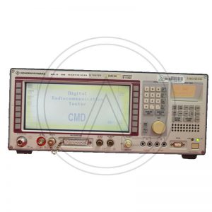
The Digital Radiocommunication Tester is an advanced top-class instrument for measurements on base stations (BTS) and BTS modules.
The LCD display with softkeys on both sides allows menu-guided convenient callup of test routines.
These testers combine compact size with high measurement accuracy and speed. They are suitable both for stationary and mobile use and feature great ease of operation and high reliability. Operation is extremely easy and requires no detailed GSM knowledge.
CMD allows measurements on transmitters and receivers of base stations without affecting telephone calls in progress.
The Rohde & Schwarz CMD60 addresses all aspects of test and measurement applications from production and service to development and quality assurance. It comes equipped with remote control via IEEE488/IEC625 bus + RS232, automated regression and stress testing of DUT, and automatic go/no go testing of fixed and portable part.Additional Features:
High production output at low investment for test equipment
The R&S® CMD60 can be remote controlled via IEC/IEEE-bus interface using SCPI-compatible commands.
Comprehensive test capabilities implemented in one single unit.
Comprehensive in-depth measurements based on ETSI Rec. CTR06
Automatic regression and stress tests
The tester supplies a great number of DECT-specific signals such as bit clock, TX/RX enable, to control the module under test
Comprehensive audio tests
Ergonomic user interface and relaxed manual operation due to a large bright LCD (requires noDECT-specific knowledge) strictly separated from the expert user interface for configuration
Integrated tools such as a scope display for power and FM demodulation versus time ease troubleshootingSKU: n/a -
Rohde & Schwarz ESHS10
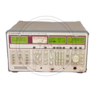
R&S ESHS10 EMI Test Receivers, 10: 9 kHz to 30 MHz
The receivers ESHS 10 is suitables for measuring electromagnetic interference in line with commercial standards:
• CISPR16, VDE0876 and ANSI C63.2
• EN55011 to 55022, ETS, FCC, VCCI and VDE 0871 to 0879 and ANSI C63.4The instruments are ideal for routine tasks in industry such as development and approval tests in line with commercial standards. Featuring mains-independent battery powering, they are also suitable for mobile applications at EMC service providers, test houses and safety standard authorities.
Superior circuit design
• High measurement accuracy, typical error 0.5 dB
• Wide dynamic range, typical noise figure 7 dB with preamplifier, third-order intercept point 20 dBm (without preamplifier)
• Calibrated attenuator with high pulse loading capacity, switchable in 10-dB steps from 0 to 120 dB
• Comprehensive preselection filters
• Switchable preamplifier with wide dynamic range
• Crystal-stabilized, fast synthesizer with high resolution and sweep mode for fast frequency scanning
• High-level mixer with high oscillator rejection
• Delay-equalized IF filtersDemodulation
• Parallel detectors for average, peak and quasi-peak indication
• 60 dB operating range also for quasipeak and average value indication
• Highly linear envelope detector with more than 70 dB dynamic range
• AM and A0 demodulators (ESVS also FM)
• Logarithmic amplifier with more than 70 dB dynamic range
• Peak indication with automatic consideration of IF bandwidth correction values for broadband interference measurements
• Automatic overload detection in mixer stages and in test channel by permanently activated peak detectorsPowerful processor system
• Manual operation or internal or external processor control
• Flash EPROMs for convenient and fast firmware update through PC
• Macros for automatic and semiautomatic test runs
• Automatic level calibration
• Automatic consideration of frequencydependent transducer factors
• All built-in functions fully programmable via IEC/IEE bus
• Fast measurement in external trigger mode; output of up to 5000 values/s via IEC/IEEE bus, up to 400 values/s including frequency change within certain frequency bands
• 12-bit A/D converter with short conversion time, measurement time selectable between 1 ms and 100 s
• High measurement accuracy thanks to automatic total calibration
• Automatic monitoring of all synthesizer loops and supply voltages during operationOptimum result display and printout
• Measurement of voltage, field strength, current and pulse spectral density with display of relevant units
• Indication of result on analog meter or digital display with 0.1 dB resolution
• Output of results as lists and diagrams on printer including limit linesFurther features
• Digital level indication on LCD and analog level indication on moving-coil meter taking into account transducer factors and their units
• Numerous interfaces for driving or feeding additional devices
• AC supply as well as battery powering for mobile applications
DatasheetSKU: n/a -
Power Meter
ROHDE & SCHWARZ NRVS
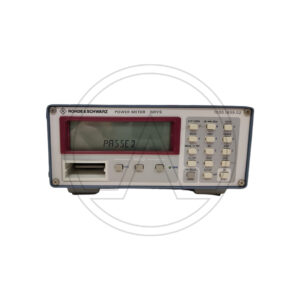
Uncompromizing technology and
ease of operation make the NRVS an
ideal instrument for any kind of power
measurement in manifold laboratory
and system applications. Thanks to its
unique measuring heads with calibra-
tion data memory and temperature
sensor, which make adjustments by
the user superfluous, the NRVS meas-
ures at all times with high accuracy
and free of operator’s errors.
The range of measuring heads includes thermal power sensors as well as highly sensitive diode power sensors, peak power
sensors, probes and insertion units for voltage measurements. The NRVS covers a power span from 100 pW up to the
kW range. In addition to the power sensors, all voltage probes of the URV5-Z series can be used.
DatasheetSKU: n/a -
Open Switch and Control Platform
ROHDE & SCHWARZ OSP150
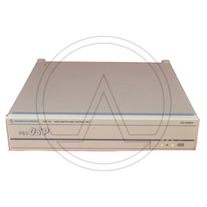
The modular R&S OSP open switch and control platform can be used to perform RF switch and control tasks.
* Compact size requiring little space
* Optimal configuration by selecting the appropriate switch and control modules
* Plug & play makes complex installation superfluous
* three module slots on the back and two on the front
* Electromechanical RF relays DC to 67 GHz
* RF solid-state relays (SSR) 9 kHz to 10 GHz
* Digital I/O and multiplexer modules
* Special switch and control modules
DatasheetSKU: n/a -
Signal Generator
ROHDE & SCHWARZ SML03
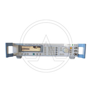
he RSSML signal generators offer all the functionalities of a state-of-the-art, general-purpose signal generators: wide frequency range, large variety of modulation functions and high reliability, at an extremely attractive price. It is ideal as a flexible signal source in automatic test systems in development, servicing or production.
FEATURESSSB phase noise: <- 122 dBc (1Hz) (at f=1GHZ, .f - 20kHz) High level accuracy (deviation – 120 dBm)
High reliability through electronic attenuator
Digital frequency and level sweep
Precise DC-coupled FM enables usage as accurage VCO
Optional pulse modulator with integrated pulse generator
Three year calibration cycle
Unit Size: 427 mm high x 88 mm wide x 450 mm deep ; < 8.5 kg. DatasheetSKU: n/a -
VIDEO TEST SIGNAL GENERATOR
ROHDE & SCHWARZ SPF2
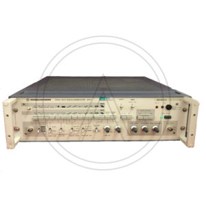
The R&S SPF2 Video Test Signal Generator produces all the video signals for TV measurements in accordance with exisiing standards or with special waveforms and amplitudes and inserts these as test lines into the program signal.
The composite colour video signal (CCVS) for full-field measurements can have standard levels or the amplitudes of the individual signal components, such as sync pulse, picture component and composite (colour) video, can be adjusted.
The SPF2 combines a number of instrument functions: video signa l generator, test signal generator, noise generator, VTR test signal generator and test signal inserter.
* Standards B/G, D, H, I (PAL) and M (NTSC)
* Video signal generator
* Noise Generator
* VTR test signal generator
* Test signal generator
* Test signal inserterSKU: n/a -
ROHDE & SCWARZ CMS52
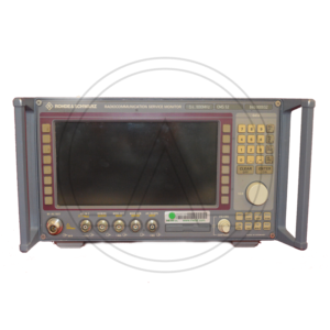
ROHDE & SCWARZ CMS52 RADIOCOMMUNICATION SERVICE MONITOR 0.4 to 1000 MHz
Options included:
B1/B2 > OCXO
B39 > Transf., Contr., Interf.
B59 > DuplexThe CMS radiocommunication service monitor is the ideal radio tester for use in service, maintenance, and test departments. It is suitable for all transceivers using AM, FM or, jM as well as SSB.
Optional extensions enable the CMS to satisfy all requirements of radio measurements and even to cover related fields.
Low weight, compact size, and low power consumption make this instrument particularly suitable for mobile use. Whether stationary or mobile, the CMS with its extensive test facilities always provides a valuable service.
The CMS uses a high-contrast, backlit LCD screen with high resolution and is operated via softkeys. A clear menu structure allows fast and direct access to all measurement facilities.
With the autorun control and printer interface, automatic test routines can easily be configured and stored via the front-panel keypad. Tolerances can be inserted into these test routines to determine and log pass/fail limits.
Battery-backed memory cards are used as program and test report library. Test reports, program lists, and screen hardcopies can be output on a printer.
The CMS is a rugged and handy unit that is particularly suitable for mobile use. It can be supplied from the local DC voltage (long operating times due to low power consumption). The results of the automatic transceiver test can be stored on a memory card for later analysis and printout.
The CMS offers great benefits to the development engineer: In a minimum of space it combines RF and AF generators as well as analyzers with high accuracy and wide dynamic range.
Due to the comprehensive standard configuration of the individual ¸CMS models and the optional extensions tailored to specific applications, additional external measuring instruments are not required.
Signal sources
• RF synthesizer from 0.4 MHz to 1000 MHz, resolution 10 Hz, with AM, FM, jM, and multitone modulation capabilities
• Two independent modulation generators, 20 Hz to 30 kHz each, resolution 0.1 Hz
• Selective-call coder for all standards (also user-programmable)
• CDCSS coder
• DTMF coder
• 10 MHz reference frequency input/output
• VOR/ILS signal generatorMeasuring facilities
• RF frequency counter, RF frequencyoffset counter
• RF power meter from 1 mW to 100 W
• Selective RF power meter down to –100 dBm
• RF spectrum monitor with wide dynamic range and filters that also allow modulation analysis (AM, FM, SSB)
• Tracking generator in frequency range from 400 kHz to 1000 MHz
• Adjacent-channel power meter with standard ETSI filters
• Modulation meter for AM, FM, and jM; detectors: +PK, –PK, PK HOLD, ±PK/2, RMS, RMS √2
• Duplex modulation meter for duplex spacings of any size
• AF voltmeter with peak and true RMS weighting
• SINAD meter with variable test frequency
• S/N meter
• Distortion meter with variable test frequency
• AF frequency counter with period and gate-time counting
• Selective-call decoder for all standards (also user-programmable)
• DTMF decoder
• Oscilloscope
• DC ammeter/voltmeter T
• ransient recorder for analysis of power and frequency transients
• SSB menus
• Harmonic measurements
• Cable fault finder
DatasheetSKU: n/a -
Power Supply
SORENSEN DCS8-125
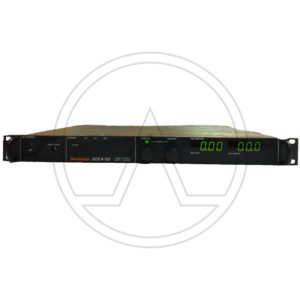
Programmable POWER SUPPLY 0-8 VOLTS 0-125 AMPS.
he DCS80-125 is a 1000 Watt DC Power Supply from Sorensen. Supplies DC voltage and current to test, design, and troubleshoot electric and electronic circuits.
This unit has a 8V and 125A.
The DCS Family of 1 kW, 1.2 kW and 3 kW programmable power supplies utilize switch-mode technology to achieve high power density in a low profile chassis. Utilizing unique packaging techniques, the DCS Family provides continuous full output power (1 kW, 1.2 kW or 3 kW) in any volt/amp combination within the rated output voltage and current limits. This family has 10-turn potentiometers to adjust voltage and current settings that are displayed simultaneously. LEDs indicate overtemperature, remote programming, shutdown and overvoltage protection, status and constant-voltage/current mode operation.
The DCS 3 kW Models have push button control of the output standby mode, OVP reset, remote/ local programming and preview status of voltage, current and OVP setpoints.
DatasheetSKU: n/a -
Power Supply
SORENSEN DCS80-13
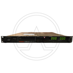
Programmable POWER SUPPLY 0-80 VOLTS 0-13 AMPS
The DCS80-13E is a 1000 Watt DC Power Supply from Sorensen. Supplies DC voltage and current to test, design, and troubleshoot electric and electronic circuits.
This unit has a 80V and 13A.
The DCS Family of 1 kW, 1.2 kW and 3 kW programmable power supplies utilize switch-mode technology to achieve high power density in a low profile chassis. Utilizing unique packaging techniques, the DCS Family provides continuous full output power (1 kW, 1.2 kW or 3 kW) in any volt/amp combination within the rated output voltage and current limits. This family has 10-turn potentiometers to adjust voltage and current settings that are displayed simultaneously. LEDs indicate overtemperature, remote programming, shutdown and overvoltage protection, status and constant-voltage/current mode operation.
The DCS 3 kW Models have push button control of the output standby mode, OVP reset, remote/ local programming and preview status of voltage, current and OVP setpoints.
DatasheetSKU: n/a -
Power Supply
TDK-Lambda GEN-60-40-1P230
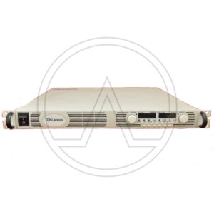
Programmable Lab Power Supply 0-60 V DC 0-40 A
This 2400 W lab power supply sets new standards. They are currently the most powerful 1 HU lab power supplies on the market. Another advantage is that you can stack one device on top of another which means that it needs no air slit either above or below and can actually get by on 1 HU.
Output voltages of up to 60 V and output currents of up to 40 A can be adjusted directly on the device or remotely via the built-in RS232/RS485 interface. All important functions can also be programmed via analogue inputs (control voltage 0 5V, 0-10V, control current 4-20 mA or via external resistor; relevant drivers are available for the digital control e.g., via LabView and LabWindows). High-resolution 16-bit A/D and D/A converters enable very precise settings and programming; the dial controls on the device can be switched between coarse and fine adjustment.
A dual digital display shows the current values, and various status information (andOver Voltage Protection, Under Voltage Limit, overload mode, address settings again), and a monitor output provides corresponding analog voltages (0 – 5 V or 0 – 10 V) for an external monitoring The device can naturally be operated as a constant voltage as well as a constant current source and can, if necessary, automatically switch between these operating modes. Several devices can be switched serially or in parallel. This GEN/H model is half the structural shape of 19″ racks.
DatasheetSKU: n/a -
SMAPLING MODULE
TEKTRONIX 80E04
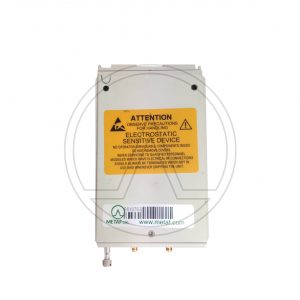
I moduli 80E10, 80E08 e 80E04 sono moduli di campionamento Time Domain Reflectometry (TDR) a doppio canale, che forniscono fino a 12 ps di incidente e 15 ps di tempo di salita riflesso nell'80E10 (18 ps di incidente in 80E08 e 23 ps di incidente in 80E04). Ciascun canale di questi moduli è in grado di generare un passo veloce per l'uso in modalità TDR e la parte di acquisizione del modulo di campionamento monitora il passo incidente e l'eventuale energia riflessa.
La polarità del passo di ogni canale può essere selezionata indipendentemente. Ciò consente il test TDR o S-parameter di modo comune o differenziale di due linee accoppiate, oltre al test indipendente di linee isolate. La generazione di passi indipendenti per ciascun canale consente misurazioni differenziali reali, che garantiscono l'accuratezza della misurazione per i dispositivi differenziali.
L'80E10 e l'80E08 sono sistemi di campionamento remoto indipendenti da 2 metri di fattore di forma ridotto e completamente integrati, che consentono la posizione del campionatore vicino al DUT e garantiscono la migliore fedeltà del segnale. Un extender opzionale da 2 metri è disponibile per l'80E04.
I moduli caratterizzano la diafonia utilizzando i passaggi TDR per pilotare una linea (o coppia di linee per la diafonia differenziale) mentre
monitorare una seconda linea (o coppia di linee) con l'altro canale (o un altro modulo per la diafonia differenziale). La funzione “filtro” sui mainframe della serie 8200 e 8000 può essere utilizzata con misurazioni TDR o diafonia per caratterizzare le prestazioni del sistema previste con frequenze di taglio inferiori.Tutti i moduli hanno un passo incidente indipendente e un raddrizzamento del ricevitore per rimuovere l'effetto dei dispositivi di misurazione e delle sonde, consentendo un disinserimento più rapido e semplice dei dispositivi di prova. I moduli di campionamento 80E10 forniscono un tempo di salita dell'acquisizione di 7 ps, con una larghezza di banda equivalente selezionabile dall'utente fino a 50 GHz (con impostazioni di 50, 40 e 30 GHz). La larghezza di banda di campionamento 80E08 è 30 GHz (selezionabile dall'utente con impostazioni 30 e 20 GHz) e la larghezza di banda di campionamento 80E04 è 20 GHz. Le sonde TDR differenziali a passo variabile P8018 da 20 GHz single-ended e P80318 da 18 GHz offrono prestazioni e conformità eccellenti, garantendo misurazioni del backplane e del pacchetto facili e accurate.
Quando l'utente utilizza questi moduli con il software Tektronix IConnect® TDR e VNA, può acquisire fino a 1.000.000 di punti dati e ottenere fino a 50 GHz differenziali, in modalità mista e parametri S single-ended.
Scheda TecnicaSKU: n/a -
Oscilloscope 2 channels
TEKTRONIX TBS1202C
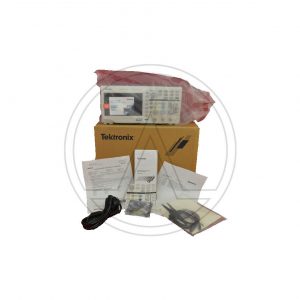
The TBS1000C Series Digital Storage Oscilloscope offers affordable performance in a compact design. It is designed to meet the needs of today's educational institutions, embedded design engineers, and maker community.
The instrument includes a 7-inch WVGA color display with up to 1 GS/s sample rate, bandwidths from 50 MHz to 200 MHz and a five-year warranty.
The instrument comes with an innovative courseware system that integrates the lab exercises with step-by-step instructions for use, by the students.Features:
7-inch WVGA color display with 15 horizontal divisions that shows 50% more signal
32 automated measurements
Dual window FFT with simultaneous time and frequency domain views
Trigger frequency counter
Pan and Zoom capability
Multi-language user interface with support for 10 languages in the user
interface and front panel overlay
Small footprint and light weight
Fanless design contributes to low noise operation
DatasheetSKU: n/a -
Power Supply
TEKTRONIX 1011A
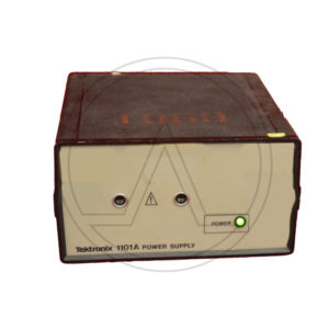
POWER SUPPLY.
The 1101A has two power receptacles that will power up to two independent probes.
The 1101A is a power supply provides external power to probes when the oscilloscope used does not have the capability to supply probe power.Two external probe power supplies
87-128/174-250 Vac; 48-440 Hz operation
Selectable 50 ohm, termination for use with 50 Ohm or 1 Mohm inputs
Overload protected
Variable DC offset, up to ±200 V
Compatible with the P6201, P6202A and P6230SKU: n/a -
Analog Waveform Monitor
TEKTRONIX 1745A
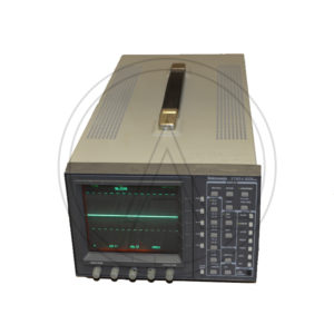
The 1740A/1750A/1760 Series make up a family of analog video waveform/vector monitors with progressive features in support of today’s demanding television environment.
Each model in the series provides improved video performance and ease of operation and incorporates application-specific features. The family includes the 1740A Series composite analog waveform/vector monitors, the 1750A Series, which adds SCH and color frame verification capabilities, and the 1760 Series for mixed-format component/composite applications.
(While the 1740A and 1750A do provide basic component waveform monitoring capabilities with parade and overlay displays, only the 1760 provides full component monitoring capabilities.)
Each series includes models for NTSC, PAL, or dual-standard NTSC/PAL operation. For NTSC models, the last digit of the model number is ’0’ (1740A, 1750A, or 1760); ’1’ for PAL (1741A, 1751A, or 1761); and ’5’ for dual-standard NTSC/PAL (1745A, 1755A, or 1765). The family features a common, straightforward operator interface, allowing the operator to take immediate advantage of the instrument’s extensive feature set. Each operating mode provides a full set of operating controls, clearly labeled and within easy reach. Key controls are always available, with bezel buttons and knobs identified by intuitive on-screen labels.SKU: n/a€600.00 View Product -
Oscilloscope 2 channels
TEKTRONIX 2230
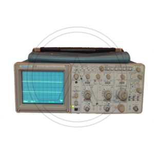
The Tektronix 2230 is a portable 100 MHz, dual-channel combination analog / digital storage scope, sister model of 2220 and 2221.
It has both an analog mode and a digital mode. In the digital storage mode, up to three waveform sets (CH 1 and/or CH 2) may be stored in a save ref. memory and recalled for display at a later time.
The 2230 features alphanumeric CRT readout of many of the front panel controls. It has a DB-9 auxiliary connector on the right side providing an external clock input as well as an output for an analog X-Y plotter to make permanent copies of the display. This feature can be accessed through the “Mem select” menu.
Some Firmware versions have a diagnostics menu with the Tektronix logo and wizard image.Vertical —
Input impedance 1 MΩ // 20 pF
Maximum Safe Input Voltage 400 V (dc + peak AC) or 800 Vp-p AC
CMRR At least 10:1 at 10 MHz
— Horizontal —
Timebase A 50 ns/Div to 0.5 s/Div, 1-2-5, x10 magnifier, i.e. down to 5 ns/Div. In “Store” mode lower sweep speeds up to 5 s/Div are available
Timebase B 50 ns/Div to 5 s/Div, 1-2-5, x10 magnifier, i.e. down to 5 ns/Div
Bandwidth 100 MHz (analog)
Sampling rate 20 MS/s
Record length 1K or 4K samples (single channel), optional 26K
Z axis input (intensity); DC to 20 MHz, maximum safe input 30V (dc + peak ac) Input resistance about 10kΩ
CRT display area : 8 × 10 cm²
Dimensions With feet and handle: 137 x 361 x 511 mm³
Features · X-Y operation
· Pre/Post-triggering
· Averaging
· Dual time base
· Cursors and readout
DatasheetSKU: n/a -
OSCILLOSCOPE COUNTER / TIMER / MULTIMETER
TEKTRONIX 2236
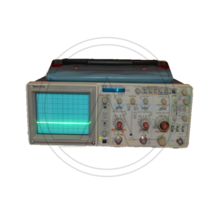
The Tektronix 2236 is a 100 MHz portable scope with a dual time base and a built-in DMM/counter with a dedicated 9-digit VF display. Apart from the counter, it is the same as the 2235.
In addition to signal frequency and period, the counter can measure delay time and delta time from the delayed timebase.
Bandwidth 90 MHz at 2 mV/Div, 100 MHz at 5 mV/Div and above; switchable 20 MHz limit
Rise time 3.9 ns at 2 mV/Div, 3.5 ns at 5 mV/Div and above
Deflection 2 mV/Div to 5 V/Div, 1−2−5, ±2%, and variable 2.5:1
Time base 50 ns/Div to 500 ms/Div (B timebase to 50 ms/Div), 1−2−5, ×10 magnifier for fastest deflection of 5 ns/Div
Frequency counter 7 digit resolution; frequency 100 Hz to 100 MHz in decade ranges, period 100 μs to 1 s in decade ranges, plus 5 s range; time base accuracy 1×10⁻⁵ (Opt.14: 5×10⁻⁷), sensitivity same as trigger specs
Multimeter 3¾ digit resolution, ≥2.5 measurements per second, 10 MΩ input resistance, input isolated from scope ground; DC volts 0.5 V to 500 V in decade ranges; AC volts RMS 0.5 V to 350 V in decade ranges; resistance 50 Ω to 50 MΩ in decade ranges, plus 200 MΩ and 2 GΩ ranges; temperature -62 °C to +230 °C (with P6602 probe)
Input impedance 1 MΩ // 20 pF
Trigger sensitivity 0.3 Div or 35 mV up to 10 MHz, 1 Div or 120 mV up to 60 MHz, 1.5 Div or 200 mV up to 100 MHz
CRT 80×100 mm² display area, P31 phosphor, 14 kV acceleration voltage
Power 90−250 VAC, 48 to 440 Hz, 40 W
Size 137 mm × 328 mm × 440 mm (5.4″ × 12.9″ × 17.3″)
Weight 5.2 kg (11.5 lb) without accessories
FeaturesDMM and counter
Delayed timebase
X−Y mode
Z input
DatasheetSKU: n/a -
Oscilloscope 4 channles
TEKTRONIX 2246A
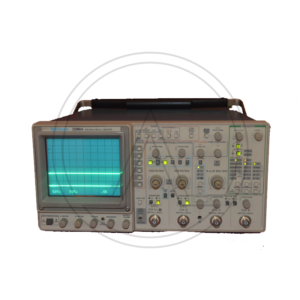
The Tektronix 2246 is a 100 MHz four-channel analog oscilloscope. Channels 1-2 are fully-functional, whereas 3-4 are limited in both deflection factor and coupling, as they are intended mainly for digital and trigger signals.
The 2246 includes many of the same features of the 2245A and adds auto tracking SmartCursors which track the selected measurment, trigger level, or ground. There are Labeled Volts Cursors with Ground-Referenced Readings and On-Screen Readouts; Hands-Off Voltmeter Measurements of DC Volts, +Peak and -Peak Volts, and P-P Volts; SmartCursors Integrate Voltage, Time, Frequency, and Phase Measurements, and are available in ALT and B Horizontal Modes.
Bandwidth 100 MHz
Deflection CH 1, CH 2: 2 mV/div to 5 V/div in 1-2-5 seq; CH 3, CH 4: 0.1 V/div and 0.5 V/div, all ±2%; BW Limit: 20 MHz ±15%
Vertical Operating Modes CH1,2,3,4, CH2 Invert, Add, Alt, Chop (625 kHz)
Input Impedance 1 MΩ ±1.0% // 20 pF ±1 pF
Maximum Input Voltage 400 V (DC + peak AC) or 800 V (p-p ac at ≤ 10 kHz)
Sweep Speeds A Time Base: 0.5 s/div to 20 ns/div in 1-2-5 seq; B Time Base: 5 ms/div to 20 ns/div in 1-2-5 seq (×10 magnifier to 2 ns/div)
Trigger DC, Noise Reject, HF Reject, LF Reject, AC, TV Line, TV Field
Trigger Modes A Mode: Auto Level, Auto, Norm, TV Line, TV Field, Single Seq. B Mode: Runs After Delay, Auto Level, Norm, TV Line (From A Source)
Trigger Source A & B Vert, CH1, 2, 3, 4, Line
Voltmeter DC, +Peak, −Peak, PK-PK, Gated Volts, Smart Tracking Cursors: Volts, Gnd, Trigger Lvl
Cursors Time, 1/Time, Delta Time, 1/Delta Time, Delta Phase, Volts
Interface Ext Counter/Timer Base Input connector; Ext Z-Axis Input connector
Probes Two P6109 100 MHz ×10 probes, BNC Connector with a readout pin.
Power 100 W max, 90 − 250 VAC, 48 − 445 Hz
DatasheetSKU: n/a -
Oscilloscope 2 channels
TEKTRONIX 2430
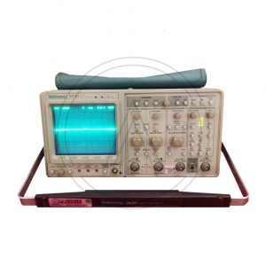
The 2430 is a 150 MHz, 2 channel digital oscilloscope from Tektronix. Measure voltage or current signals over time in an electronic circuit or component to display amplitude, frequency and rise times, etc. Applications include troubleshooting, production test, and design.
Additional Features:
Bandwidth: 150 MHz
2 Channels
Sample Rate: 100MS/s
Dual Timebase
2mV/div- 5V/div
Auto Setup, Auto Measure, Auto Pass/Fail, and Auto Sequencing.
SKU: n/a
-
Digital Radiocommunication Tester
ROHDE & SCHWARZ CMD60
The Digital Radiocommunication Tester is an advanced top-class instrument for measurements on base stations (BTS) and BTS modules.
The LCD display with softkeys on both sides allows menu-guided convenient callup of test routines.
These testers combine compact size with high measurement accuracy and speed. They are suitable both for stationary and mobile use and feature great ease of operation and high reliability. Operation is extremely easy and requires no detailed GSM knowledge.
CMD allows measurements on transmitters and receivers of base stations without affecting telephone calls in progress.
The Rohde & Schwarz CMD60 addresses all aspects of test and measurement applications from production and service to development and quality assurance. It comes equipped with remote control via IEEE488/IEC625 bus + RS232, automated regression and stress testing of DUT, and automatic go/no go testing of fixed and portable part.Additional Features:
High production output at low investment for test equipment
The R&S® CMD60 can be remote controlled via IEC/IEEE-bus interface using SCPI-compatible commands.
Comprehensive test capabilities implemented in one single unit.
Comprehensive in-depth measurements based on ETSI Rec. CTR06
Automatic regression and stress tests
The tester supplies a great number of DECT-specific signals such as bit clock, TX/RX enable, to control the module under test
Comprehensive audio tests
Ergonomic user interface and relaxed manual operation due to a large bright LCD (requires noDECT-specific knowledge) strictly separated from the expert user interface for configuration
Integrated tools such as a scope display for power and FM demodulation versus time ease troubleshooting -
Rohde & Schwarz ESHS10
R&S ESHS10 EMI Test Receivers, 10: 9 kHz to 30 MHz
The receivers ESHS 10 is suitables for measuring electromagnetic interference in line with commercial standards:
• CISPR16, VDE0876 and ANSI C63.2
• EN55011 to 55022, ETS, FCC, VCCI and VDE 0871 to 0879 and ANSI C63.4The instruments are ideal for routine tasks in industry such as development and approval tests in line with commercial standards. Featuring mains-independent battery powering, they are also suitable for mobile applications at EMC service providers, test houses and safety standard authorities.
Superior circuit design
• High measurement accuracy, typical error 0.5 dB
• Wide dynamic range, typical noise figure 7 dB with preamplifier, third-order intercept point 20 dBm (without preamplifier)
• Calibrated attenuator with high pulse loading capacity, switchable in 10-dB steps from 0 to 120 dB
• Comprehensive preselection filters
• Switchable preamplifier with wide dynamic range
• Crystal-stabilized, fast synthesizer with high resolution and sweep mode for fast frequency scanning
• High-level mixer with high oscillator rejection
• Delay-equalized IF filtersDemodulation
• Parallel detectors for average, peak and quasi-peak indication
• 60 dB operating range also for quasipeak and average value indication
• Highly linear envelope detector with more than 70 dB dynamic range
• AM and A0 demodulators (ESVS also FM)
• Logarithmic amplifier with more than 70 dB dynamic range
• Peak indication with automatic consideration of IF bandwidth correction values for broadband interference measurements
• Automatic overload detection in mixer stages and in test channel by permanently activated peak detectorsPowerful processor system
• Manual operation or internal or external processor control
• Flash EPROMs for convenient and fast firmware update through PC
• Macros for automatic and semiautomatic test runs
• Automatic level calibration
• Automatic consideration of frequencydependent transducer factors
• All built-in functions fully programmable via IEC/IEE bus
• Fast measurement in external trigger mode; output of up to 5000 values/s via IEC/IEEE bus, up to 400 values/s including frequency change within certain frequency bands
• 12-bit A/D converter with short conversion time, measurement time selectable between 1 ms and 100 s
• High measurement accuracy thanks to automatic total calibration
• Automatic monitoring of all synthesizer loops and supply voltages during operationOptimum result display and printout
• Measurement of voltage, field strength, current and pulse spectral density with display of relevant units
• Indication of result on analog meter or digital display with 0.1 dB resolution
• Output of results as lists and diagrams on printer including limit linesFurther features
• Digital level indication on LCD and analog level indication on moving-coil meter taking into account transducer factors and their units
• Numerous interfaces for driving or feeding additional devices
• AC supply as well as battery powering for mobile applications
Datasheet -
Power Meter
ROHDE & SCHWARZ NRVS
Uncompromizing technology and
ease of operation make the NRVS an
ideal instrument for any kind of power
measurement in manifold laboratory
and system applications. Thanks to its
unique measuring heads with calibra-
tion data memory and temperature
sensor, which make adjustments by
the user superfluous, the NRVS meas-
ures at all times with high accuracy
and free of operator’s errors.
The range of measuring heads includes thermal power sensors as well as highly sensitive diode power sensors, peak power
sensors, probes and insertion units for voltage measurements. The NRVS covers a power span from 100 pW up to the
kW range. In addition to the power sensors, all voltage probes of the URV5-Z series can be used.
Datasheet -
Open Switch and Control Platform
ROHDE & SCHWARZ OSP150
The modular R&S OSP open switch and control platform can be used to perform RF switch and control tasks.
* Compact size requiring little space
* Optimal configuration by selecting the appropriate switch and control modules
* Plug & play makes complex installation superfluous
* three module slots on the back and two on the front
* Electromechanical RF relays DC to 67 GHz
* RF solid-state relays (SSR) 9 kHz to 10 GHz
* Digital I/O and multiplexer modules
* Special switch and control modules
Datasheet -
Signal Generator
ROHDE & SCHWARZ SML03
he RSSML signal generators offer all the functionalities of a state-of-the-art, general-purpose signal generators: wide frequency range, large variety of modulation functions and high reliability, at an extremely attractive price. It is ideal as a flexible signal source in automatic test systems in development, servicing or production.
FEATURESSSB phase noise: <- 122 dBc (1Hz) (at f=1GHZ, .f - 20kHz) High level accuracy (deviation – 120 dBm)
High reliability through electronic attenuator
Digital frequency and level sweep
Precise DC-coupled FM enables usage as accurage VCO
Optional pulse modulator with integrated pulse generator
Three year calibration cycle
Unit Size: 427 mm high x 88 mm wide x 450 mm deep ; < 8.5 kg. Datasheet -
VIDEO TEST SIGNAL GENERATOR
ROHDE & SCHWARZ SPF2
The R&S SPF2 Video Test Signal Generator produces all the video signals for TV measurements in accordance with exisiing standards or with special waveforms and amplitudes and inserts these as test lines into the program signal.
The composite colour video signal (CCVS) for full-field measurements can have standard levels or the amplitudes of the individual signal components, such as sync pulse, picture component and composite (colour) video, can be adjusted.
The SPF2 combines a number of instrument functions: video signa l generator, test signal generator, noise generator, VTR test signal generator and test signal inserter.
* Standards B/G, D, H, I (PAL) and M (NTSC)
* Video signal generator
* Noise Generator
* VTR test signal generator
* Test signal generator
* Test signal inserter -
ROHDE & SCWARZ CMS52
ROHDE & SCWARZ CMS52 RADIOCOMMUNICATION SERVICE MONITOR 0.4 to 1000 MHz
Options included:
B1/B2 > OCXO
B39 > Transf., Contr., Interf.
B59 > DuplexThe CMS radiocommunication service monitor is the ideal radio tester for use in service, maintenance, and test departments. It is suitable for all transceivers using AM, FM or, jM as well as SSB.
Optional extensions enable the CMS to satisfy all requirements of radio measurements and even to cover related fields.
Low weight, compact size, and low power consumption make this instrument particularly suitable for mobile use. Whether stationary or mobile, the CMS with its extensive test facilities always provides a valuable service.
The CMS uses a high-contrast, backlit LCD screen with high resolution and is operated via softkeys. A clear menu structure allows fast and direct access to all measurement facilities.
With the autorun control and printer interface, automatic test routines can easily be configured and stored via the front-panel keypad. Tolerances can be inserted into these test routines to determine and log pass/fail limits.
Battery-backed memory cards are used as program and test report library. Test reports, program lists, and screen hardcopies can be output on a printer.
The CMS is a rugged and handy unit that is particularly suitable for mobile use. It can be supplied from the local DC voltage (long operating times due to low power consumption). The results of the automatic transceiver test can be stored on a memory card for later analysis and printout.
The CMS offers great benefits to the development engineer: In a minimum of space it combines RF and AF generators as well as analyzers with high accuracy and wide dynamic range.
Due to the comprehensive standard configuration of the individual ¸CMS models and the optional extensions tailored to specific applications, additional external measuring instruments are not required.
Signal sources
• RF synthesizer from 0.4 MHz to 1000 MHz, resolution 10 Hz, with AM, FM, jM, and multitone modulation capabilities
• Two independent modulation generators, 20 Hz to 30 kHz each, resolution 0.1 Hz
• Selective-call coder for all standards (also user-programmable)
• CDCSS coder
• DTMF coder
• 10 MHz reference frequency input/output
• VOR/ILS signal generatorMeasuring facilities
• RF frequency counter, RF frequencyoffset counter
• RF power meter from 1 mW to 100 W
• Selective RF power meter down to –100 dBm
• RF spectrum monitor with wide dynamic range and filters that also allow modulation analysis (AM, FM, SSB)
• Tracking generator in frequency range from 400 kHz to 1000 MHz
• Adjacent-channel power meter with standard ETSI filters
• Modulation meter for AM, FM, and jM; detectors: +PK, –PK, PK HOLD, ±PK/2, RMS, RMS √2
• Duplex modulation meter for duplex spacings of any size
• AF voltmeter with peak and true RMS weighting
• SINAD meter with variable test frequency
• S/N meter
• Distortion meter with variable test frequency
• AF frequency counter with period and gate-time counting
• Selective-call decoder for all standards (also user-programmable)
• DTMF decoder
• Oscilloscope
• DC ammeter/voltmeter T
• ransient recorder for analysis of power and frequency transients
• SSB menus
• Harmonic measurements
• Cable fault finder
Datasheet -
Power Supply
SORENSEN DCS8-125
Programmable POWER SUPPLY 0-8 VOLTS 0-125 AMPS.
he DCS80-125 is a 1000 Watt DC Power Supply from Sorensen. Supplies DC voltage and current to test, design, and troubleshoot electric and electronic circuits.
This unit has a 8V and 125A.
The DCS Family of 1 kW, 1.2 kW and 3 kW programmable power supplies utilize switch-mode technology to achieve high power density in a low profile chassis. Utilizing unique packaging techniques, the DCS Family provides continuous full output power (1 kW, 1.2 kW or 3 kW) in any volt/amp combination within the rated output voltage and current limits. This family has 10-turn potentiometers to adjust voltage and current settings that are displayed simultaneously. LEDs indicate overtemperature, remote programming, shutdown and overvoltage protection, status and constant-voltage/current mode operation.
The DCS 3 kW Models have push button control of the output standby mode, OVP reset, remote/ local programming and preview status of voltage, current and OVP setpoints.
Datasheet -
Power Supply
SORENSEN DCS80-13
Programmable POWER SUPPLY 0-80 VOLTS 0-13 AMPS
The DCS80-13E is a 1000 Watt DC Power Supply from Sorensen. Supplies DC voltage and current to test, design, and troubleshoot electric and electronic circuits.
This unit has a 80V and 13A.
The DCS Family of 1 kW, 1.2 kW and 3 kW programmable power supplies utilize switch-mode technology to achieve high power density in a low profile chassis. Utilizing unique packaging techniques, the DCS Family provides continuous full output power (1 kW, 1.2 kW or 3 kW) in any volt/amp combination within the rated output voltage and current limits. This family has 10-turn potentiometers to adjust voltage and current settings that are displayed simultaneously. LEDs indicate overtemperature, remote programming, shutdown and overvoltage protection, status and constant-voltage/current mode operation.
The DCS 3 kW Models have push button control of the output standby mode, OVP reset, remote/ local programming and preview status of voltage, current and OVP setpoints.
Datasheet -
Power Supply
TDK-Lambda GEN-60-40-1P230
Programmable Lab Power Supply 0-60 V DC 0-40 A
This 2400 W lab power supply sets new standards. They are currently the most powerful 1 HU lab power supplies on the market. Another advantage is that you can stack one device on top of another which means that it needs no air slit either above or below and can actually get by on 1 HU.
Output voltages of up to 60 V and output currents of up to 40 A can be adjusted directly on the device or remotely via the built-in RS232/RS485 interface. All important functions can also be programmed via analogue inputs (control voltage 0 5V, 0-10V, control current 4-20 mA or via external resistor; relevant drivers are available for the digital control e.g., via LabView and LabWindows). High-resolution 16-bit A/D and D/A converters enable very precise settings and programming; the dial controls on the device can be switched between coarse and fine adjustment.
A dual digital display shows the current values, and various status information (andOver Voltage Protection, Under Voltage Limit, overload mode, address settings again), and a monitor output provides corresponding analog voltages (0 – 5 V or 0 – 10 V) for an external monitoring The device can naturally be operated as a constant voltage as well as a constant current source and can, if necessary, automatically switch between these operating modes. Several devices can be switched serially or in parallel. This GEN/H model is half the structural shape of 19″ racks.
Datasheet -
SMAPLING MODULE
TEKTRONIX 80E04
I moduli 80E10, 80E08 e 80E04 sono moduli di campionamento Time Domain Reflectometry (TDR) a doppio canale, che forniscono fino a 12 ps di incidente e 15 ps di tempo di salita riflesso nell'80E10 (18 ps di incidente in 80E08 e 23 ps di incidente in 80E04). Ciascun canale di questi moduli è in grado di generare un passo veloce per l'uso in modalità TDR e la parte di acquisizione del modulo di campionamento monitora il passo incidente e l'eventuale energia riflessa.
La polarità del passo di ogni canale può essere selezionata indipendentemente. Ciò consente il test TDR o S-parameter di modo comune o differenziale di due linee accoppiate, oltre al test indipendente di linee isolate. La generazione di passi indipendenti per ciascun canale consente misurazioni differenziali reali, che garantiscono l'accuratezza della misurazione per i dispositivi differenziali.
L'80E10 e l'80E08 sono sistemi di campionamento remoto indipendenti da 2 metri di fattore di forma ridotto e completamente integrati, che consentono la posizione del campionatore vicino al DUT e garantiscono la migliore fedeltà del segnale. Un extender opzionale da 2 metri è disponibile per l'80E04.
I moduli caratterizzano la diafonia utilizzando i passaggi TDR per pilotare una linea (o coppia di linee per la diafonia differenziale) mentre
monitorare una seconda linea (o coppia di linee) con l'altro canale (o un altro modulo per la diafonia differenziale). La funzione “filtro” sui mainframe della serie 8200 e 8000 può essere utilizzata con misurazioni TDR o diafonia per caratterizzare le prestazioni del sistema previste con frequenze di taglio inferiori.Tutti i moduli hanno un passo incidente indipendente e un raddrizzamento del ricevitore per rimuovere l'effetto dei dispositivi di misurazione e delle sonde, consentendo un disinserimento più rapido e semplice dei dispositivi di prova. I moduli di campionamento 80E10 forniscono un tempo di salita dell'acquisizione di 7 ps, con una larghezza di banda equivalente selezionabile dall'utente fino a 50 GHz (con impostazioni di 50, 40 e 30 GHz). La larghezza di banda di campionamento 80E08 è 30 GHz (selezionabile dall'utente con impostazioni 30 e 20 GHz) e la larghezza di banda di campionamento 80E04 è 20 GHz. Le sonde TDR differenziali a passo variabile P8018 da 20 GHz single-ended e P80318 da 18 GHz offrono prestazioni e conformità eccellenti, garantendo misurazioni del backplane e del pacchetto facili e accurate.
Quando l'utente utilizza questi moduli con il software Tektronix IConnect® TDR e VNA, può acquisire fino a 1.000.000 di punti dati e ottenere fino a 50 GHz differenziali, in modalità mista e parametri S single-ended.
Scheda Tecnica -
Oscilloscope 2 channels
TEKTRONIX TBS1202C
The TBS1000C Series Digital Storage Oscilloscope offers affordable performance in a compact design. It is designed to meet the needs of today's educational institutions, embedded design engineers, and maker community.
The instrument includes a 7-inch WVGA color display with up to 1 GS/s sample rate, bandwidths from 50 MHz to 200 MHz and a five-year warranty.
The instrument comes with an innovative courseware system that integrates the lab exercises with step-by-step instructions for use, by the students.Features:
7-inch WVGA color display with 15 horizontal divisions that shows 50% more signal
32 automated measurements
Dual window FFT with simultaneous time and frequency domain views
Trigger frequency counter
Pan and Zoom capability
Multi-language user interface with support for 10 languages in the user
interface and front panel overlay
Small footprint and light weight
Fanless design contributes to low noise operation
Datasheet -
Power Supply
TEKTRONIX 1011A
POWER SUPPLY.
The 1101A has two power receptacles that will power up to two independent probes.
The 1101A is a power supply provides external power to probes when the oscilloscope used does not have the capability to supply probe power.Two external probe power supplies
87-128/174-250 Vac; 48-440 Hz operation
Selectable 50 ohm, termination for use with 50 Ohm or 1 Mohm inputs
Overload protected
Variable DC offset, up to ±200 V
Compatible with the P6201, P6202A and P6230 -
Analog Waveform Monitor
TEKTRONIX 1745A
The 1740A/1750A/1760 Series make up a family of analog video waveform/vector monitors with progressive features in support of today’s demanding television environment.
Each model in the series provides improved video performance and ease of operation and incorporates application-specific features. The family includes the 1740A Series composite analog waveform/vector monitors, the 1750A Series, which adds SCH and color frame verification capabilities, and the 1760 Series for mixed-format component/composite applications.
(While the 1740A and 1750A do provide basic component waveform monitoring capabilities with parade and overlay displays, only the 1760 provides full component monitoring capabilities.)
Each series includes models for NTSC, PAL, or dual-standard NTSC/PAL operation. For NTSC models, the last digit of the model number is ’0’ (1740A, 1750A, or 1760); ’1’ for PAL (1741A, 1751A, or 1761); and ’5’ for dual-standard NTSC/PAL (1745A, 1755A, or 1765). The family features a common, straightforward operator interface, allowing the operator to take immediate advantage of the instrument’s extensive feature set. Each operating mode provides a full set of operating controls, clearly labeled and within easy reach. Key controls are always available, with bezel buttons and knobs identified by intuitive on-screen labels. -
Oscilloscope 2 channels
TEKTRONIX 2230
The Tektronix 2230 is a portable 100 MHz, dual-channel combination analog / digital storage scope, sister model of 2220 and 2221.
It has both an analog mode and a digital mode. In the digital storage mode, up to three waveform sets (CH 1 and/or CH 2) may be stored in a save ref. memory and recalled for display at a later time.
The 2230 features alphanumeric CRT readout of many of the front panel controls. It has a DB-9 auxiliary connector on the right side providing an external clock input as well as an output for an analog X-Y plotter to make permanent copies of the display. This feature can be accessed through the “Mem select” menu.
Some Firmware versions have a diagnostics menu with the Tektronix logo and wizard image.Vertical —
Input impedance 1 MΩ // 20 pF
Maximum Safe Input Voltage 400 V (dc + peak AC) or 800 Vp-p AC
CMRR At least 10:1 at 10 MHz
— Horizontal —
Timebase A 50 ns/Div to 0.5 s/Div, 1-2-5, x10 magnifier, i.e. down to 5 ns/Div. In “Store” mode lower sweep speeds up to 5 s/Div are available
Timebase B 50 ns/Div to 5 s/Div, 1-2-5, x10 magnifier, i.e. down to 5 ns/Div
Bandwidth 100 MHz (analog)
Sampling rate 20 MS/s
Record length 1K or 4K samples (single channel), optional 26K
Z axis input (intensity); DC to 20 MHz, maximum safe input 30V (dc + peak ac) Input resistance about 10kΩ
CRT display area : 8 × 10 cm²
Dimensions With feet and handle: 137 x 361 x 511 mm³
Features · X-Y operation
· Pre/Post-triggering
· Averaging
· Dual time base
· Cursors and readout
Datasheet -
OSCILLOSCOPE COUNTER / TIMER / MULTIMETER
TEKTRONIX 2236
The Tektronix 2236 is a 100 MHz portable scope with a dual time base and a built-in DMM/counter with a dedicated 9-digit VF display. Apart from the counter, it is the same as the 2235.
In addition to signal frequency and period, the counter can measure delay time and delta time from the delayed timebase.
Bandwidth 90 MHz at 2 mV/Div, 100 MHz at 5 mV/Div and above; switchable 20 MHz limit
Rise time 3.9 ns at 2 mV/Div, 3.5 ns at 5 mV/Div and above
Deflection 2 mV/Div to 5 V/Div, 1−2−5, ±2%, and variable 2.5:1
Time base 50 ns/Div to 500 ms/Div (B timebase to 50 ms/Div), 1−2−5, ×10 magnifier for fastest deflection of 5 ns/Div
Frequency counter 7 digit resolution; frequency 100 Hz to 100 MHz in decade ranges, period 100 μs to 1 s in decade ranges, plus 5 s range; time base accuracy 1×10⁻⁵ (Opt.14: 5×10⁻⁷), sensitivity same as trigger specs
Multimeter 3¾ digit resolution, ≥2.5 measurements per second, 10 MΩ input resistance, input isolated from scope ground; DC volts 0.5 V to 500 V in decade ranges; AC volts RMS 0.5 V to 350 V in decade ranges; resistance 50 Ω to 50 MΩ in decade ranges, plus 200 MΩ and 2 GΩ ranges; temperature -62 °C to +230 °C (with P6602 probe)
Input impedance 1 MΩ // 20 pF
Trigger sensitivity 0.3 Div or 35 mV up to 10 MHz, 1 Div or 120 mV up to 60 MHz, 1.5 Div or 200 mV up to 100 MHz
CRT 80×100 mm² display area, P31 phosphor, 14 kV acceleration voltage
Power 90−250 VAC, 48 to 440 Hz, 40 W
Size 137 mm × 328 mm × 440 mm (5.4″ × 12.9″ × 17.3″)
Weight 5.2 kg (11.5 lb) without accessories
FeaturesDMM and counter
Delayed timebase
X−Y mode
Z input
Datasheet -
Oscilloscope 4 channles
TEKTRONIX 2246A
The Tektronix 2246 is a 100 MHz four-channel analog oscilloscope. Channels 1-2 are fully-functional, whereas 3-4 are limited in both deflection factor and coupling, as they are intended mainly for digital and trigger signals.
The 2246 includes many of the same features of the 2245A and adds auto tracking SmartCursors which track the selected measurment, trigger level, or ground. There are Labeled Volts Cursors with Ground-Referenced Readings and On-Screen Readouts; Hands-Off Voltmeter Measurements of DC Volts, +Peak and -Peak Volts, and P-P Volts; SmartCursors Integrate Voltage, Time, Frequency, and Phase Measurements, and are available in ALT and B Horizontal Modes.
Bandwidth 100 MHz
Deflection CH 1, CH 2: 2 mV/div to 5 V/div in 1-2-5 seq; CH 3, CH 4: 0.1 V/div and 0.5 V/div, all ±2%; BW Limit: 20 MHz ±15%
Vertical Operating Modes CH1,2,3,4, CH2 Invert, Add, Alt, Chop (625 kHz)
Input Impedance 1 MΩ ±1.0% // 20 pF ±1 pF
Maximum Input Voltage 400 V (DC + peak AC) or 800 V (p-p ac at ≤ 10 kHz)
Sweep Speeds A Time Base: 0.5 s/div to 20 ns/div in 1-2-5 seq; B Time Base: 5 ms/div to 20 ns/div in 1-2-5 seq (×10 magnifier to 2 ns/div)
Trigger DC, Noise Reject, HF Reject, LF Reject, AC, TV Line, TV Field
Trigger Modes A Mode: Auto Level, Auto, Norm, TV Line, TV Field, Single Seq. B Mode: Runs After Delay, Auto Level, Norm, TV Line (From A Source)
Trigger Source A & B Vert, CH1, 2, 3, 4, Line
Voltmeter DC, +Peak, −Peak, PK-PK, Gated Volts, Smart Tracking Cursors: Volts, Gnd, Trigger Lvl
Cursors Time, 1/Time, Delta Time, 1/Delta Time, Delta Phase, Volts
Interface Ext Counter/Timer Base Input connector; Ext Z-Axis Input connector
Probes Two P6109 100 MHz ×10 probes, BNC Connector with a readout pin.
Power 100 W max, 90 − 250 VAC, 48 − 445 Hz
Datasheet -
Oscilloscope 2 channels
TEKTRONIX 2430
The 2430 is a 150 MHz, 2 channel digital oscilloscope from Tektronix. Measure voltage or current signals over time in an electronic circuit or component to display amplitude, frequency and rise times, etc. Applications include troubleshooting, production test, and design.
Additional Features:
Bandwidth: 150 MHz
2 Channels
Sample Rate: 100MS/s
Dual Timebase
2mV/div- 5V/div
Auto Setup, Auto Measure, Auto Pass/Fail, and Auto Sequencing.
-
Digital Radiocommunication Tester
ROHDE & SCHWARZ CMD60
The Digital Radiocommunication Tester is an advanced top-class instrument for measurements on base stations (BTS) and BTS modules.
The LCD display with softkeys on both sides allows menu-guided convenient callup of test routines.
These testers combine compact size with high measurement accuracy and speed. They are suitable both for stationary and mobile use and feature great ease of operation and high reliability. Operation is extremely easy and requires no detailed GSM knowledge.
CMD allows measurements on transmitters and receivers of base stations without affecting telephone calls in progress.
The Rohde & Schwarz CMD60 addresses all aspects of test and measurement applications from production and service to development and quality assurance. It comes equipped with remote control via IEEE488/IEC625 bus + RS232, automated regression and stress testing of DUT, and automatic go/no go testing of fixed and portable part.Additional Features:
High production output at low investment for test equipment
The R&S® CMD60 can be remote controlled via IEC/IEEE-bus interface using SCPI-compatible commands.
Comprehensive test capabilities implemented in one single unit.
Comprehensive in-depth measurements based on ETSI Rec. CTR06
Automatic regression and stress tests
The tester supplies a great number of DECT-specific signals such as bit clock, TX/RX enable, to control the module under test
Comprehensive audio tests
Ergonomic user interface and relaxed manual operation due to a large bright LCD (requires noDECT-specific knowledge) strictly separated from the expert user interface for configuration
Integrated tools such as a scope display for power and FM demodulation versus time ease troubleshooting -
Rohde & Schwarz ESHS10
R&S ESHS10 EMI Test Receivers, 10: 9 kHz to 30 MHz
The receivers ESHS 10 is suitables for measuring electromagnetic interference in line with commercial standards:
• CISPR16, VDE0876 and ANSI C63.2
• EN55011 to 55022, ETS, FCC, VCCI and VDE 0871 to 0879 and ANSI C63.4The instruments are ideal for routine tasks in industry such as development and approval tests in line with commercial standards. Featuring mains-independent battery powering, they are also suitable for mobile applications at EMC service providers, test houses and safety standard authorities.
Superior circuit design
• High measurement accuracy, typical error 0.5 dB
• Wide dynamic range, typical noise figure 7 dB with preamplifier, third-order intercept point 20 dBm (without preamplifier)
• Calibrated attenuator with high pulse loading capacity, switchable in 10-dB steps from 0 to 120 dB
• Comprehensive preselection filters
• Switchable preamplifier with wide dynamic range
• Crystal-stabilized, fast synthesizer with high resolution and sweep mode for fast frequency scanning
• High-level mixer with high oscillator rejection
• Delay-equalized IF filtersDemodulation
• Parallel detectors for average, peak and quasi-peak indication
• 60 dB operating range also for quasipeak and average value indication
• Highly linear envelope detector with more than 70 dB dynamic range
• AM and A0 demodulators (ESVS also FM)
• Logarithmic amplifier with more than 70 dB dynamic range
• Peak indication with automatic consideration of IF bandwidth correction values for broadband interference measurements
• Automatic overload detection in mixer stages and in test channel by permanently activated peak detectorsPowerful processor system
• Manual operation or internal or external processor control
• Flash EPROMs for convenient and fast firmware update through PC
• Macros for automatic and semiautomatic test runs
• Automatic level calibration
• Automatic consideration of frequencydependent transducer factors
• All built-in functions fully programmable via IEC/IEE bus
• Fast measurement in external trigger mode; output of up to 5000 values/s via IEC/IEEE bus, up to 400 values/s including frequency change within certain frequency bands
• 12-bit A/D converter with short conversion time, measurement time selectable between 1 ms and 100 s
• High measurement accuracy thanks to automatic total calibration
• Automatic monitoring of all synthesizer loops and supply voltages during operationOptimum result display and printout
• Measurement of voltage, field strength, current and pulse spectral density with display of relevant units
• Indication of result on analog meter or digital display with 0.1 dB resolution
• Output of results as lists and diagrams on printer including limit linesFurther features
• Digital level indication on LCD and analog level indication on moving-coil meter taking into account transducer factors and their units
• Numerous interfaces for driving or feeding additional devices
• AC supply as well as battery powering for mobile applications
Datasheet -
Power Meter
ROHDE & SCHWARZ NRVS
Uncompromizing technology and
ease of operation make the NRVS an
ideal instrument for any kind of power
measurement in manifold laboratory
and system applications. Thanks to its
unique measuring heads with calibra-
tion data memory and temperature
sensor, which make adjustments by
the user superfluous, the NRVS meas-
ures at all times with high accuracy
and free of operator’s errors.
The range of measuring heads includes thermal power sensors as well as highly sensitive diode power sensors, peak power
sensors, probes and insertion units for voltage measurements. The NRVS covers a power span from 100 pW up to the
kW range. In addition to the power sensors, all voltage probes of the URV5-Z series can be used.
Datasheet -
Open Switch and Control Platform
ROHDE & SCHWARZ OSP150
The modular R&S OSP open switch and control platform can be used to perform RF switch and control tasks.
* Compact size requiring little space
* Optimal configuration by selecting the appropriate switch and control modules
* Plug & play makes complex installation superfluous
* three module slots on the back and two on the front
* Electromechanical RF relays DC to 67 GHz
* RF solid-state relays (SSR) 9 kHz to 10 GHz
* Digital I/O and multiplexer modules
* Special switch and control modules
Datasheet -
Signal Generator
ROHDE & SCHWARZ SML03
he RSSML signal generators offer all the functionalities of a state-of-the-art, general-purpose signal generators: wide frequency range, large variety of modulation functions and high reliability, at an extremely attractive price. It is ideal as a flexible signal source in automatic test systems in development, servicing or production.
FEATURESSSB phase noise: <- 122 dBc (1Hz) (at f=1GHZ, .f - 20kHz) High level accuracy (deviation – 120 dBm)
High reliability through electronic attenuator
Digital frequency and level sweep
Precise DC-coupled FM enables usage as accurage VCO
Optional pulse modulator with integrated pulse generator
Three year calibration cycle
Unit Size: 427 mm high x 88 mm wide x 450 mm deep ; < 8.5 kg. Datasheet -
VIDEO TEST SIGNAL GENERATOR
ROHDE & SCHWARZ SPF2
The R&S SPF2 Video Test Signal Generator produces all the video signals for TV measurements in accordance with exisiing standards or with special waveforms and amplitudes and inserts these as test lines into the program signal.
The composite colour video signal (CCVS) for full-field measurements can have standard levels or the amplitudes of the individual signal components, such as sync pulse, picture component and composite (colour) video, can be adjusted.
The SPF2 combines a number of instrument functions: video signa l generator, test signal generator, noise generator, VTR test signal generator and test signal inserter.
* Standards B/G, D, H, I (PAL) and M (NTSC)
* Video signal generator
* Noise Generator
* VTR test signal generator
* Test signal generator
* Test signal inserter -
ROHDE & SCWARZ CMS52
ROHDE & SCWARZ CMS52 RADIOCOMMUNICATION SERVICE MONITOR 0.4 to 1000 MHz
Options included:
B1/B2 > OCXO
B39 > Transf., Contr., Interf.
B59 > DuplexThe CMS radiocommunication service monitor is the ideal radio tester for use in service, maintenance, and test departments. It is suitable for all transceivers using AM, FM or, jM as well as SSB.
Optional extensions enable the CMS to satisfy all requirements of radio measurements and even to cover related fields.
Low weight, compact size, and low power consumption make this instrument particularly suitable for mobile use. Whether stationary or mobile, the CMS with its extensive test facilities always provides a valuable service.
The CMS uses a high-contrast, backlit LCD screen with high resolution and is operated via softkeys. A clear menu structure allows fast and direct access to all measurement facilities.
With the autorun control and printer interface, automatic test routines can easily be configured and stored via the front-panel keypad. Tolerances can be inserted into these test routines to determine and log pass/fail limits.
Battery-backed memory cards are used as program and test report library. Test reports, program lists, and screen hardcopies can be output on a printer.
The CMS is a rugged and handy unit that is particularly suitable for mobile use. It can be supplied from the local DC voltage (long operating times due to low power consumption). The results of the automatic transceiver test can be stored on a memory card for later analysis and printout.
The CMS offers great benefits to the development engineer: In a minimum of space it combines RF and AF generators as well as analyzers with high accuracy and wide dynamic range.
Due to the comprehensive standard configuration of the individual ¸CMS models and the optional extensions tailored to specific applications, additional external measuring instruments are not required.
Signal sources
• RF synthesizer from 0.4 MHz to 1000 MHz, resolution 10 Hz, with AM, FM, jM, and multitone modulation capabilities
• Two independent modulation generators, 20 Hz to 30 kHz each, resolution 0.1 Hz
• Selective-call coder for all standards (also user-programmable)
• CDCSS coder
• DTMF coder
• 10 MHz reference frequency input/output
• VOR/ILS signal generatorMeasuring facilities
• RF frequency counter, RF frequencyoffset counter
• RF power meter from 1 mW to 100 W
• Selective RF power meter down to –100 dBm
• RF spectrum monitor with wide dynamic range and filters that also allow modulation analysis (AM, FM, SSB)
• Tracking generator in frequency range from 400 kHz to 1000 MHz
• Adjacent-channel power meter with standard ETSI filters
• Modulation meter for AM, FM, and jM; detectors: +PK, –PK, PK HOLD, ±PK/2, RMS, RMS √2
• Duplex modulation meter for duplex spacings of any size
• AF voltmeter with peak and true RMS weighting
• SINAD meter with variable test frequency
• S/N meter
• Distortion meter with variable test frequency
• AF frequency counter with period and gate-time counting
• Selective-call decoder for all standards (also user-programmable)
• DTMF decoder
• Oscilloscope
• DC ammeter/voltmeter T
• ransient recorder for analysis of power and frequency transients
• SSB menus
• Harmonic measurements
• Cable fault finder
Datasheet -
Power Supply
SORENSEN DCS8-125
Programmable POWER SUPPLY 0-8 VOLTS 0-125 AMPS.
he DCS80-125 is a 1000 Watt DC Power Supply from Sorensen. Supplies DC voltage and current to test, design, and troubleshoot electric and electronic circuits.
This unit has a 8V and 125A.
The DCS Family of 1 kW, 1.2 kW and 3 kW programmable power supplies utilize switch-mode technology to achieve high power density in a low profile chassis. Utilizing unique packaging techniques, the DCS Family provides continuous full output power (1 kW, 1.2 kW or 3 kW) in any volt/amp combination within the rated output voltage and current limits. This family has 10-turn potentiometers to adjust voltage and current settings that are displayed simultaneously. LEDs indicate overtemperature, remote programming, shutdown and overvoltage protection, status and constant-voltage/current mode operation.
The DCS 3 kW Models have push button control of the output standby mode, OVP reset, remote/ local programming and preview status of voltage, current and OVP setpoints.
Datasheet -
Power Supply
SORENSEN DCS80-13
Programmable POWER SUPPLY 0-80 VOLTS 0-13 AMPS
The DCS80-13E is a 1000 Watt DC Power Supply from Sorensen. Supplies DC voltage and current to test, design, and troubleshoot electric and electronic circuits.
This unit has a 80V and 13A.
The DCS Family of 1 kW, 1.2 kW and 3 kW programmable power supplies utilize switch-mode technology to achieve high power density in a low profile chassis. Utilizing unique packaging techniques, the DCS Family provides continuous full output power (1 kW, 1.2 kW or 3 kW) in any volt/amp combination within the rated output voltage and current limits. This family has 10-turn potentiometers to adjust voltage and current settings that are displayed simultaneously. LEDs indicate overtemperature, remote programming, shutdown and overvoltage protection, status and constant-voltage/current mode operation.
The DCS 3 kW Models have push button control of the output standby mode, OVP reset, remote/ local programming and preview status of voltage, current and OVP setpoints.
Datasheet -
Power Supply
TDK-Lambda GEN-60-40-1P230
Programmable Lab Power Supply 0-60 V DC 0-40 A
This 2400 W lab power supply sets new standards. They are currently the most powerful 1 HU lab power supplies on the market. Another advantage is that you can stack one device on top of another which means that it needs no air slit either above or below and can actually get by on 1 HU.
Output voltages of up to 60 V and output currents of up to 40 A can be adjusted directly on the device or remotely via the built-in RS232/RS485 interface. All important functions can also be programmed via analogue inputs (control voltage 0 5V, 0-10V, control current 4-20 mA or via external resistor; relevant drivers are available for the digital control e.g., via LabView and LabWindows). High-resolution 16-bit A/D and D/A converters enable very precise settings and programming; the dial controls on the device can be switched between coarse and fine adjustment.
A dual digital display shows the current values, and various status information (andOver Voltage Protection, Under Voltage Limit, overload mode, address settings again), and a monitor output provides corresponding analog voltages (0 – 5 V or 0 – 10 V) for an external monitoring The device can naturally be operated as a constant voltage as well as a constant current source and can, if necessary, automatically switch between these operating modes. Several devices can be switched serially or in parallel. This GEN/H model is half the structural shape of 19″ racks.
Datasheet -
SMAPLING MODULE
TEKTRONIX 80E04
I moduli 80E10, 80E08 e 80E04 sono moduli di campionamento Time Domain Reflectometry (TDR) a doppio canale, che forniscono fino a 12 ps di incidente e 15 ps di tempo di salita riflesso nell'80E10 (18 ps di incidente in 80E08 e 23 ps di incidente in 80E04). Ciascun canale di questi moduli è in grado di generare un passo veloce per l'uso in modalità TDR e la parte di acquisizione del modulo di campionamento monitora il passo incidente e l'eventuale energia riflessa.
La polarità del passo di ogni canale può essere selezionata indipendentemente. Ciò consente il test TDR o S-parameter di modo comune o differenziale di due linee accoppiate, oltre al test indipendente di linee isolate. La generazione di passi indipendenti per ciascun canale consente misurazioni differenziali reali, che garantiscono l'accuratezza della misurazione per i dispositivi differenziali.
L'80E10 e l'80E08 sono sistemi di campionamento remoto indipendenti da 2 metri di fattore di forma ridotto e completamente integrati, che consentono la posizione del campionatore vicino al DUT e garantiscono la migliore fedeltà del segnale. Un extender opzionale da 2 metri è disponibile per l'80E04.
I moduli caratterizzano la diafonia utilizzando i passaggi TDR per pilotare una linea (o coppia di linee per la diafonia differenziale) mentre
monitorare una seconda linea (o coppia di linee) con l'altro canale (o un altro modulo per la diafonia differenziale). La funzione “filtro” sui mainframe della serie 8200 e 8000 può essere utilizzata con misurazioni TDR o diafonia per caratterizzare le prestazioni del sistema previste con frequenze di taglio inferiori.Tutti i moduli hanno un passo incidente indipendente e un raddrizzamento del ricevitore per rimuovere l'effetto dei dispositivi di misurazione e delle sonde, consentendo un disinserimento più rapido e semplice dei dispositivi di prova. I moduli di campionamento 80E10 forniscono un tempo di salita dell'acquisizione di 7 ps, con una larghezza di banda equivalente selezionabile dall'utente fino a 50 GHz (con impostazioni di 50, 40 e 30 GHz). La larghezza di banda di campionamento 80E08 è 30 GHz (selezionabile dall'utente con impostazioni 30 e 20 GHz) e la larghezza di banda di campionamento 80E04 è 20 GHz. Le sonde TDR differenziali a passo variabile P8018 da 20 GHz single-ended e P80318 da 18 GHz offrono prestazioni e conformità eccellenti, garantendo misurazioni del backplane e del pacchetto facili e accurate.
Quando l'utente utilizza questi moduli con il software Tektronix IConnect® TDR e VNA, può acquisire fino a 1.000.000 di punti dati e ottenere fino a 50 GHz differenziali, in modalità mista e parametri S single-ended.
Scheda Tecnica -
Oscilloscope 2 channels
TEKTRONIX TBS1202C
The TBS1000C Series Digital Storage Oscilloscope offers affordable performance in a compact design. It is designed to meet the needs of today's educational institutions, embedded design engineers, and maker community.
The instrument includes a 7-inch WVGA color display with up to 1 GS/s sample rate, bandwidths from 50 MHz to 200 MHz and a five-year warranty.
The instrument comes with an innovative courseware system that integrates the lab exercises with step-by-step instructions for use, by the students.Features:
7-inch WVGA color display with 15 horizontal divisions that shows 50% more signal
32 automated measurements
Dual window FFT with simultaneous time and frequency domain views
Trigger frequency counter
Pan and Zoom capability
Multi-language user interface with support for 10 languages in the user
interface and front panel overlay
Small footprint and light weight
Fanless design contributes to low noise operation
Datasheet -
Power Supply
TEKTRONIX 1011A
POWER SUPPLY.
The 1101A has two power receptacles that will power up to two independent probes.
The 1101A is a power supply provides external power to probes when the oscilloscope used does not have the capability to supply probe power.Two external probe power supplies
87-128/174-250 Vac; 48-440 Hz operation
Selectable 50 ohm, termination for use with 50 Ohm or 1 Mohm inputs
Overload protected
Variable DC offset, up to ±200 V
Compatible with the P6201, P6202A and P6230 -
Analog Waveform Monitor
TEKTRONIX 1745A
The 1740A/1750A/1760 Series make up a family of analog video waveform/vector monitors with progressive features in support of today’s demanding television environment.
Each model in the series provides improved video performance and ease of operation and incorporates application-specific features. The family includes the 1740A Series composite analog waveform/vector monitors, the 1750A Series, which adds SCH and color frame verification capabilities, and the 1760 Series for mixed-format component/composite applications.
(While the 1740A and 1750A do provide basic component waveform monitoring capabilities with parade and overlay displays, only the 1760 provides full component monitoring capabilities.)
Each series includes models for NTSC, PAL, or dual-standard NTSC/PAL operation. For NTSC models, the last digit of the model number is ’0’ (1740A, 1750A, or 1760); ’1’ for PAL (1741A, 1751A, or 1761); and ’5’ for dual-standard NTSC/PAL (1745A, 1755A, or 1765). The family features a common, straightforward operator interface, allowing the operator to take immediate advantage of the instrument’s extensive feature set. Each operating mode provides a full set of operating controls, clearly labeled and within easy reach. Key controls are always available, with bezel buttons and knobs identified by intuitive on-screen labels.€600.00 View Product -
Oscilloscope 2 channels
TEKTRONIX 2230
The Tektronix 2230 is a portable 100 MHz, dual-channel combination analog / digital storage scope, sister model of 2220 and 2221.
It has both an analog mode and a digital mode. In the digital storage mode, up to three waveform sets (CH 1 and/or CH 2) may be stored in a save ref. memory and recalled for display at a later time.
The 2230 features alphanumeric CRT readout of many of the front panel controls. It has a DB-9 auxiliary connector on the right side providing an external clock input as well as an output for an analog X-Y plotter to make permanent copies of the display. This feature can be accessed through the “Mem select” menu.
Some Firmware versions have a diagnostics menu with the Tektronix logo and wizard image.Vertical —
Input impedance 1 MΩ // 20 pF
Maximum Safe Input Voltage 400 V (dc + peak AC) or 800 Vp-p AC
CMRR At least 10:1 at 10 MHz
— Horizontal —
Timebase A 50 ns/Div to 0.5 s/Div, 1-2-5, x10 magnifier, i.e. down to 5 ns/Div. In “Store” mode lower sweep speeds up to 5 s/Div are available
Timebase B 50 ns/Div to 5 s/Div, 1-2-5, x10 magnifier, i.e. down to 5 ns/Div
Bandwidth 100 MHz (analog)
Sampling rate 20 MS/s
Record length 1K or 4K samples (single channel), optional 26K
Z axis input (intensity); DC to 20 MHz, maximum safe input 30V (dc + peak ac) Input resistance about 10kΩ
CRT display area : 8 × 10 cm²
Dimensions With feet and handle: 137 x 361 x 511 mm³
Features · X-Y operation
· Pre/Post-triggering
· Averaging
· Dual time base
· Cursors and readout
Datasheet -
OSCILLOSCOPE COUNTER / TIMER / MULTIMETER
TEKTRONIX 2236
The Tektronix 2236 is a 100 MHz portable scope with a dual time base and a built-in DMM/counter with a dedicated 9-digit VF display. Apart from the counter, it is the same as the 2235.
In addition to signal frequency and period, the counter can measure delay time and delta time from the delayed timebase.
Bandwidth 90 MHz at 2 mV/Div, 100 MHz at 5 mV/Div and above; switchable 20 MHz limit
Rise time 3.9 ns at 2 mV/Div, 3.5 ns at 5 mV/Div and above
Deflection 2 mV/Div to 5 V/Div, 1−2−5, ±2%, and variable 2.5:1
Time base 50 ns/Div to 500 ms/Div (B timebase to 50 ms/Div), 1−2−5, ×10 magnifier for fastest deflection of 5 ns/Div
Frequency counter 7 digit resolution; frequency 100 Hz to 100 MHz in decade ranges, period 100 μs to 1 s in decade ranges, plus 5 s range; time base accuracy 1×10⁻⁵ (Opt.14: 5×10⁻⁷), sensitivity same as trigger specs
Multimeter 3¾ digit resolution, ≥2.5 measurements per second, 10 MΩ input resistance, input isolated from scope ground; DC volts 0.5 V to 500 V in decade ranges; AC volts RMS 0.5 V to 350 V in decade ranges; resistance 50 Ω to 50 MΩ in decade ranges, plus 200 MΩ and 2 GΩ ranges; temperature -62 °C to +230 °C (with P6602 probe)
Input impedance 1 MΩ // 20 pF
Trigger sensitivity 0.3 Div or 35 mV up to 10 MHz, 1 Div or 120 mV up to 60 MHz, 1.5 Div or 200 mV up to 100 MHz
CRT 80×100 mm² display area, P31 phosphor, 14 kV acceleration voltage
Power 90−250 VAC, 48 to 440 Hz, 40 W
Size 137 mm × 328 mm × 440 mm (5.4″ × 12.9″ × 17.3″)
Weight 5.2 kg (11.5 lb) without accessories
FeaturesDMM and counter
Delayed timebase
X−Y mode
Z input
Datasheet -
Oscilloscope 4 channles
TEKTRONIX 2246A
The Tektronix 2246 is a 100 MHz four-channel analog oscilloscope. Channels 1-2 are fully-functional, whereas 3-4 are limited in both deflection factor and coupling, as they are intended mainly for digital and trigger signals.
The 2246 includes many of the same features of the 2245A and adds auto tracking SmartCursors which track the selected measurment, trigger level, or ground. There are Labeled Volts Cursors with Ground-Referenced Readings and On-Screen Readouts; Hands-Off Voltmeter Measurements of DC Volts, +Peak and -Peak Volts, and P-P Volts; SmartCursors Integrate Voltage, Time, Frequency, and Phase Measurements, and are available in ALT and B Horizontal Modes.
Bandwidth 100 MHz
Deflection CH 1, CH 2: 2 mV/div to 5 V/div in 1-2-5 seq; CH 3, CH 4: 0.1 V/div and 0.5 V/div, all ±2%; BW Limit: 20 MHz ±15%
Vertical Operating Modes CH1,2,3,4, CH2 Invert, Add, Alt, Chop (625 kHz)
Input Impedance 1 MΩ ±1.0% // 20 pF ±1 pF
Maximum Input Voltage 400 V (DC + peak AC) or 800 V (p-p ac at ≤ 10 kHz)
Sweep Speeds A Time Base: 0.5 s/div to 20 ns/div in 1-2-5 seq; B Time Base: 5 ms/div to 20 ns/div in 1-2-5 seq (×10 magnifier to 2 ns/div)
Trigger DC, Noise Reject, HF Reject, LF Reject, AC, TV Line, TV Field
Trigger Modes A Mode: Auto Level, Auto, Norm, TV Line, TV Field, Single Seq. B Mode: Runs After Delay, Auto Level, Norm, TV Line (From A Source)
Trigger Source A & B Vert, CH1, 2, 3, 4, Line
Voltmeter DC, +Peak, −Peak, PK-PK, Gated Volts, Smart Tracking Cursors: Volts, Gnd, Trigger Lvl
Cursors Time, 1/Time, Delta Time, 1/Delta Time, Delta Phase, Volts
Interface Ext Counter/Timer Base Input connector; Ext Z-Axis Input connector
Probes Two P6109 100 MHz ×10 probes, BNC Connector with a readout pin.
Power 100 W max, 90 − 250 VAC, 48 − 445 Hz
Datasheet -
Oscilloscope 2 channels
TEKTRONIX 2430
The 2430 is a 150 MHz, 2 channel digital oscilloscope from Tektronix. Measure voltage or current signals over time in an electronic circuit or component to display amplitude, frequency and rise times, etc. Applications include troubleshooting, production test, and design.
Additional Features:
Bandwidth: 150 MHz
2 Channels
Sample Rate: 100MS/s
Dual Timebase
2mV/div- 5V/div
Auto Setup, Auto Measure, Auto Pass/Fail, and Auto Sequencing.



 Italiano


